
Lookups as fractions. A lookup argument proves that two multisets of tuples agree. In the logarithmic-derivative form of Haböck and its GKR realisation [Hab22, PH23], written LogUp-GKR, a tuple \boldsymbol f on bus \mathsf{bus} with multiplicity m contributes m/\big(\alpha-\mathsf{bus}-\sum_{j\ge1}\beta^j f_j\big) for random \alpha,\beta\in\mathbb{F}_{p^4}; senders and receivers must sum to the same value, which a layered GKR circuit [GKR08] computes and proves by sumcheck (§5.6).
Three uses of one argument. The buses ask this argument for three things, named by the distinctions introduced with Lasso [STW24] and used by Jolt [AST24]. An indexed lookup proves a_i=T[b_i] for committed indices b; an unindexed lookup proves only that each a_i occurs in T, as a range check does. An indexed lookup is a read from a read-only memory [ST25], so the program bus and the byte bus are indexed lookups into preprocessed tables, and range checks are unindexed. Registers and memory are read–write, where a lookup no longer suffices, since a read could be answered with a value written only later.
Definition 2.3 (Memory checking [ST25, §2.2]). Consider a memory of K cells, an initial content \mathit{init}\in\mathbb{F}^K and T accesses in time order, access j carrying an address a_j, a returned value v_j and a written value v'_j (for a read, v'_j=v_j). The accesses are consistent if every v_j equals v'_{j'} for the largest j'<j with a_{j'}=a_j, or \mathit{init}[a_j] if there is none. A memory-checking argument proves consistency of committed accesses; with no writes and public contents it is an indexed lookup.
Memory-checking arguments either reorder the trace by address or do not [ST25, App. A]. Ziren’s does not: it is Blum et al.’s offline check [BEG+94] with Spice’s timestamps [SAGL18]. Each access supplies the timestamp of the previous access to its address, proves it smaller than its own, and sends and receives the old and new (\mathsf{address},\mathsf{value},\mathsf{timestamp}) on a bus, so consistency becomes the balance of one multiset relation plus a range fact per access (Lemma 5.4). The timestamp is the frame’s (\mathsf{shard},\mathsf{clk}+\mathsf{pos}), already ordered by the state bus, so one range-checked difference suffices where Spice’s rule needs two. The fingerprinting error grows linearly in the number of accesses and cells [ST25, §2.7], which over \mathbb{F}_{p^4} is negligible and is charged in Section 9.2.
Ziren’s constraint system is a set of chips, tables whose rows satisfy local polynomial constraints and which communicate only through buses.
Definition 2.4 (Chip). A chip is a table over \mathbb{F} of a fixed width w together with a set of polynomial constraints of degree at most three in the w columns of one row, a distinguished boolean column \mathsf{is\_real} gating every constraint, and a set of interactions. A row is satisfying if it satisfies every constraint.
Definition 2.5 (Interaction and bus). An interaction of a chip is a triple (\mathsf{bus},\boldsymbol f,m) where \mathsf{bus} is a name, \boldsymbol f is a tuple of linear expressions in the row’s columns and m is a linear expression in the columns (the multiplicity), marked as a send or a receive. Multiplicities are non-negative integers bounded well below p: senders use zero, one, or a value range-checked against the byte table, and the preprocessed Program, Byte and Range tables receive with use counts that the shard’s cycle budget bounds by 2^{25}. For a set of tables, the multiset of a bus is \{\boldsymbol f(r)\} with multiplicity \sum m(r) over the sends of all rows r of all chips, and likewise for the receives. A bus balances if its send and receive multisets are equal.
Two facts connect balance to the fraction identity over \mathbb{F}_{p^4}. The multiplicity bound stops the counters wrapping modulo p, so balance is a statement about integer multiplicities; the exact condition is a positive total below p and a negative total above -p [Ope26a, Cor. 3.6]. And the identity is checked after compressing tuples with sampled challenges, so an unbalanced bus can still satisfy it, with probability bounded by Schwartz–Zippel; Section 9.2 charges that error.
Definition 2.6 (Shard relation). A shard is a set of tables, one per chip, together with public values \mathsf{pv}=(\mathsf{sh},\mathsf{entry},\mathsf{exit},\mathsf{cur}_{\mathrm{in}},\mathsf{cur}_{\mathrm{out}},D,h,\mathsf{code}): its shard index; its entry and exit states, each a program-counter pair with the clock; the address cursors of the global memory tables before and after it; its cross-shard digest, a point of an elliptic curve over the degree-7 extension \mathbb{F}_{p^7} (§5.5); the digest of committed output; and the exit code. It is valid for a verifying key \mathsf{vk} if its preprocessed tables are those \mathsf{vk} commits to, every real row is satisfying and every bus balances, where the public-values table contributes the entry state as a send and the exit state as a receive on the state bus, and the program bus is received by the preprocessed program table with the recorded multiplicities.
Definition 2.7 (Inputs, outputs and determinism of a chip). For a chip U, the inputs I_U(r) of a row r are the values the row consumes from elsewhere: the tuples of its receives, the program tuple it fetches, the previous-value part of its memory accesses, and its declared free values, the values its constraints leave to the prover by design, which the statements of §9.7.2 list. The outputs O_U(r) are the values it produces for elsewhere: the tuples of its sends other than the fetch, and the new-value part of its memory accesses. Fetch and previous value are sends in the sense of Definition 2.5, but inputs of the row, so the direction of an interaction is not the direction of the data. U is deterministic if for all satisfying real rows r,r', I_U(r)=I_U(r')\;\Rightarrow\;O_U(r)=O_U(r').
This is the notion of Picus [PCW+23] adapted to the interaction language.
Guest, host and cost metrics. The guest is the MIPS32 program and its runtime, whose execution is proved; guest cycles count its executed instructions. The host runs the executor and the prover, and the verifier trusts nothing it computes. The trace area of a shard or block is the sum over chips of rows × columns of the main trace, in cells; the (row, interaction) count is the number of bus interactions over all rows, the leaf count of the lookup circuit; and throughput is proved guest cycles per second of wall-clock time. Every committed value lies in the base field and costs one cell whatever its width, so instruction efficiency is improved by removing cells, not narrowing them (§1.3).
Ziren proves one statement, the execution of a MIPS32 image (§4.4), and outputs a compressed proof of it. A native verifier checks that proof as a program, natively or compiled to WebAssembly, as the consumers of the proofs published for real-time proving of Ethereum blocks do; it pays for the proof’s size and its own running time. Algorithm 1 states Ziren up to that proof and Figure 1 draws it. The subsections below annotate the algorithm and state its core as two protocols, the shard argument (Protocol 3.1) and the block argument (Protocol 3.2), symbolic in the parameters of §3.4; Sections 4–8 construct their components and Section 9 states what they establish.
Verifiers that count cost differently are served by applications built on Ziren (§3.5). Each verifies the compressed proof inside another proof system, starting from one shrink node: a wrap into a pairing-based SNARK for an on-chain verifier, an Ethereum contract that pays gas, and a binary stage and narrow recursion for a garbled verifier, a Boolean circuit that pays for its AND gates and input bits.
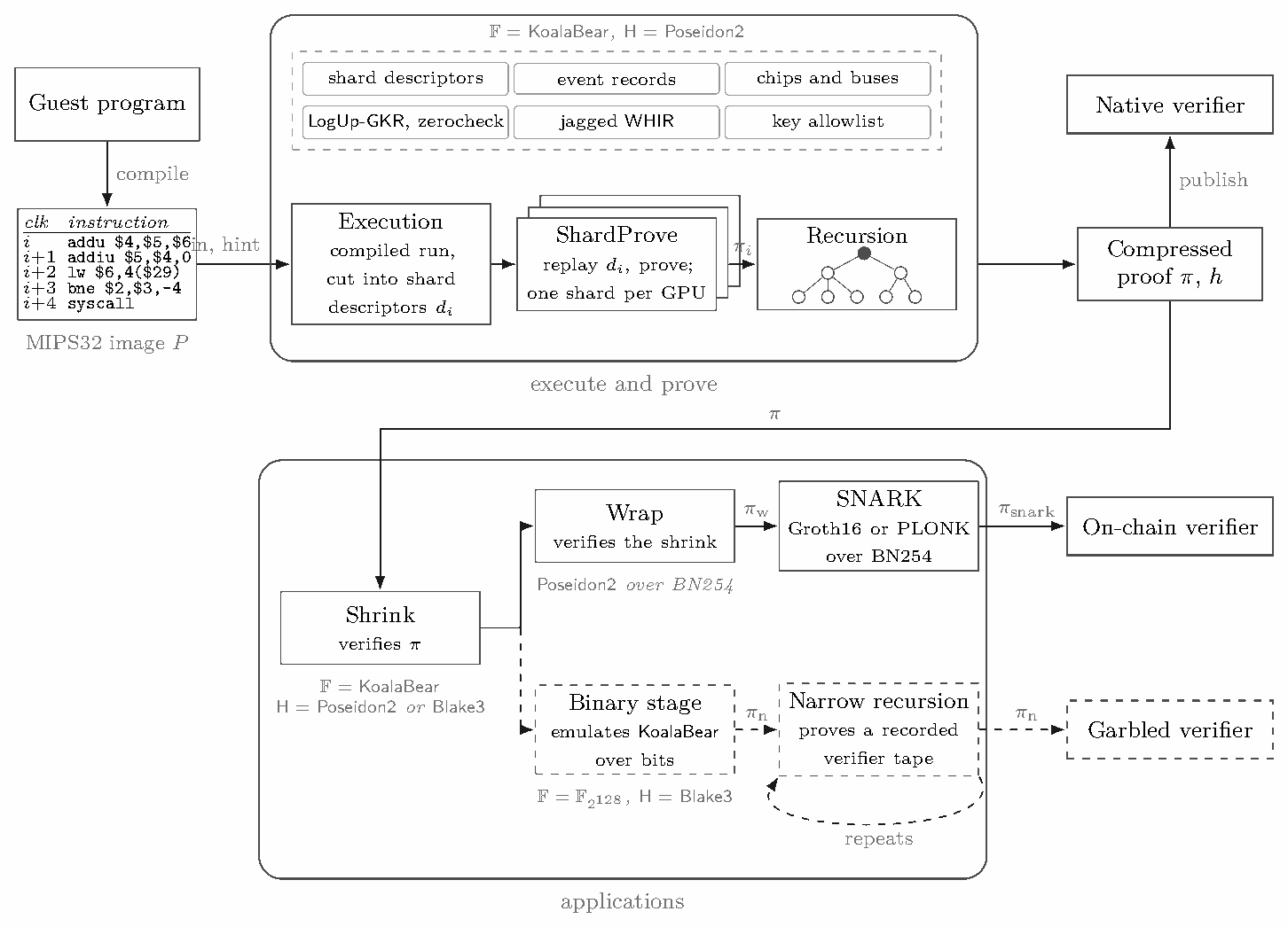
Algorithm 1: Ziren, up to the compressed proof. Lines 3–9 run as a pipeline (§3.3).
Input: a program image P; input and hint streams (\mathit{in},\mathit{hint})
Output: the compressed proof \pi
// the native verifier runs \mathsf{Verify}(\mathsf{vk},h,\pi) (Protocol 3.2)
Line 2 runs once. An interpreter implements every instruction, syscall and error path and alone emits the event record the prover consumes. A just-in-time compiler runs the guest once and cuts the run into shards, each described by the values its reads observe and its boundary registers, so a worker replays its shard under the interpreter and no event record crosses a process boundary (§4.2). The two implementations are tested against each other, not proved equal, and nothing in the protocol depends on the compiler.
Line 5 proves one shard. Chips, with one row per executed instruction, and buses arithmetise it (Section 5); their constraints and buses are designed to hold exactly when the shard is a correct piece of the execution, and the premises that remain open are listed in §9.1. A bus argument BA (LogUp-GKR, §5.6) and a constraint argument CA (a zerocheck, §5.7) reduce every claim to column evaluations at one point; a jagged commitment JC reduces those to one evaluation of one dense polynomial (§6), which one WHIR opening authenticates (§7). Protocol 3.1 states the reduction. Each step ends with evaluation claims on committed columns, so the steps compose without the verifier reading a column, and the number, widths and heights of the chips are invisible above JC.
Protocol 3.1 (Shard argument). Statement: a verifying key committing to the program and the preprocessed tables, and the public values of one shard.
Witness: the shard’s execution record.
Output: a shard proof for the public values \mathsf{pv} of Definition 2.6.
What the verifier checks. No quantity a soundness bound depends on is read from the proof beyond the declared heights, which the configuration caps (a column is at most 2^{22} rows, §6.6), and every algebraic identity the native verifier checks is also checked by the recursive verifier. The verifier (i) absorbs the verifying key, the public values and the per-chip dimensions before drawing any challenge; (ii) checks every sumcheck round of the bus argument, the constraint argument, the jagged sumcheck and the jagged assist, and each one’s closing identity, evaluating the constraint polynomials itself; (iii) checks Equation (4); (iv) runs the WHIR verifier with the query counts, folding factors and grinding bits of the schedule; and (v) checks that the public values are well formed. Preprocessed row counts come from the verifying key and the schedule from the verifier’s configuration.
Costs. With A the committed area of a shard, n_{\mathrm{int}} its number of bus interactions and K its number of columns, the prover performs O(A+n_{\mathrm{int}}) field operations outside the commitment and O(A/\rho) hashing and transform work inside it. The verifier checks O(\log^2 n_{\mathrm{int}}) sumcheck rounds for the layered lookup circuit and O(\log A) for each of the other three sumchecks, evaluates each chip’s constraints once, spends O(mK) on the jagged assist’s closing identity (Theorem 6.2), and checks the WHIR queries, whose count is fixed by the schedule. The proof size is dominated by the first WHIR round’s openings, t_0 queries times the stripes times 2^{k_0} (§7.2). Section 10 gives the concrete values.
Lines 6–9 compose the shard proofs into one proof of the arithmetised relation \mathcal{R}_{\mathrm{arith}} of §9.1, which §9.7 connects to the relation \mathcal{R} of §4.4. Leaves and compose nodes are recursion programs proved with the same shard argument, and each checks its children’s keys against an allowlist enumerated from the machine’s declared shapes (§8). Protocol 3.2 states these lines, and the native verifier, with the conditions each node checks.
Protocol 3.2 (Block proof, end to end). Public parameters: the field \mathbb{F} and extension \mathbb{F}_{p^4}, the Poseidon2 transcript and Merkle trees, the WHIR schedule (Table 5), the bucket rule (§6.6), the compose arity (at most three), and the allowlist root \mathsf{root}_K of the admissible leaf and compose keys (Algorithm 3).
\mathsf{Setup}(P). Commit to the program ROM of image P and to the preprocessed Program, Byte and Range tables; output (\mathsf{pk},\mathsf{vk}).
\mathsf{Prove}(\mathsf{pk},P,\mathit{in},\mathit{hint}).
\mathsf{Verify}(\mathsf{vk},h,\pi).
Steps 2 to 4 of \mathsf{Prove} overlap: a shard is proved as soon as its record exists and a compose node as soon as its children are proved, with trace generation and proof-of-work on the accelerators. Only the root’s proof leaves the prover, so only the root uses the schedule tuned for size (§10.4). The start-up interval and the serial composes over the last shards remain, and they account for the gap between the multi-device speed-up and linear scaling (Table 10).
The protocol is symbolic in the following parameters; numeric values are fixed where each component is built.
Query soundness needs no conjecture: it is counted in the unique-decoding regime for the core schedule and under the Johnson bound for the root’s compress schedule (§9.2).
An application verifies the compressed proof inside a proof system whose verifier its consumer can afford. Figure 1 (bottom) draws the two built on Ziren; neither changes the statement, and each output attests the same execution as \pi. This paper measures and accounts only Ziren (Algorithm 1).
The shrink. A shrink node is a recursion node that verifies the compressed proof. Both applications run the same program, proved under Poseidon2 for the wrap and under Blake3 [OANWO20], commitments and transcript alike, for garbled verification, so garbled verification changes the hash before it changes the field (§8.1).
On-chain verification. An on-chain verifier is an Ethereum contract; it pays gas, which precompiled BN254 pairings make small and independent of the statement only for a pairing-based argument over that curve with a constant-size proof [Gro16, GWC19]. A wrap node re-proves the shrink with its commitments and transcript under Poseidon2 over the BN254 scalar field, and a Groth16 or PLONK circuit over BN254 verifies the wrap proof, hashing natively; the circuit either fixes the wrap key or takes it as an input (§8.1). The on-chain verifier checks the result with a constant number of pairings.
Garbled verification. A garbled verifier is a Boolean circuit evaluated under garbling [Yao86], as in protocols that check a computation on Bitcoin only when it is disputed [Lin23]. Evaluating a garbled verifier on an invalid proof reveals a secret that serves as the fraud proof [Eag25]; later protocols build bridges on this [WAA+26], make the verification of pairing-based SNARKs far cheaper [EL26, GKS+26], and shrink the on-chain footprint of malicious security [KTA+26]. They garble the verifier of a pairing-based SNARK or of a designated-verifier variant of one, where this application garbles a hash-based verifier over a binary field. A garbled verifier pays for its AND gates and for its input bits, while XOR gates are free [KS08, ZRE15]. Over a 31-bit prime field an addition is a carry chain and a multiplication a reduction modulo p; over \mathbb{F}_{2^{128}} an addition is a XOR, so this application moves the arithmetic to a binary field and the hash to one built from word additions, XORs and rotations. The binary stage commits bit columns as packed elements of \mathbb{F}_{2^{128}} and opens them through ring switching [DP23, DP24], emulating the shrink verifier’s KoalaBear arithmetic over bits.
Its verifier is not rewritten as a circuit. A recorder runs it over a value type that appends every multiplication, inversion, bit decomposition and Blake3 hash to a tape, and every comparison as the condition it found, so the tape is fixed by the proof’s shape and key and enforces the control flow of the run that recorded it. A narrow machine native to \mathbb{F}_{2^{128}} proves a run of the tape, with a ledger of read cells and tables for arithmetic, bit rewiring and Blake3, and narrow recursion repeats the step on each narrow proof’s own verifier. The garbled circuit evaluates the last recorded tape on the bits of the last narrow proof; it pays AND gates for field products, Blake3 compressions and the per-claim tensor algebra of ring switching, and takes as input every value the proof opens and every Merkle path. The narrow machine follows from that cost: few tables, narrow ones, none reading its next row, power-of-two widths, and a low-rate opening.
This section gives enough of MIPS32 to follow the paper and states the relation Ziren proves; the specification is the architecture manual [MIP10]. The guest has no floating-point unit, privileged state or interrupts; it executes the 77 instructions of Appendix B and reaches the outside world only through SYSCALL.
Definition 4.1 (Machine state). The machine state is (\mathsf{pc},\mathsf{next\_pc},R,M). R holds 32 general registers of 32 bits, register 0 reading as zero, together with the HI/LO pair written by multiplication and division; M is a little-endian, byte-addressed memory over a 32-bit address space. \mathsf{pc} is the address of the instruction about to execute and \mathsf{next\_pc} the address of the one that executes after it, which is not in general \mathsf{pc}+4.
Definition 4.2 (Instruction format). Every instruction of the guest is decoded, once and before proving, into a tuple (\mathsf{opcode},\mathsf{op\_a},\mathsf{op\_b},\mathsf{op\_c},\mathsf{imm\_b},\mathsf{imm\_c}). \mathsf{op\_a} is the index of the register the instruction writes (or, for a store or branch, reads); \mathsf{op\_b} and \mathsf{op\_c} are each either a register index or an immediate already sign- or zero-extended to 32 bits, as the flags \mathsf{imm\_b} and \mathsf{imm\_c} say.
The decoded form abstracts MIPS32’s three encodings as Jolt’s five-tuple abstracts RISC-V’s [AST24]; the correspondence (Table 2) is fixed by the opcode and recomputable by anyone from the image. Figure 2 gives the transition of one instruction.
Table 2: From the three MIPS32 encodings to the decoded tuple of Definition 4.2. Field widths are in bits, most significant first; off and imm are 16-bit, target 26-bit and sa 5-bit. Immediates are extended when decoded, as the opcode dictates.
| Format | Fields | Instructions | (\mathsf{op\_a},\mathsf{op\_b},\mathsf{op\_c}) |
|---|---|---|---|
| R | op 6 | rs 5 | rt 5 | rd 5 | sa 5 | func 6 | register ALU | (rd, rs, rt) |
| shift by sa | (rd, rt, sa) | ||
jr, jalr |
(rd, rs, −) | ||
| I | op 6 | rs 5 | rt 5 | imm 16 | immediate ALU, loads, stores | (rt, rs, ext(imm)) |
| branches | (rs, rt, sext(off) ≪ 2) | ||
| J | op 6 | target 26 | j, jal |
(0 or 31, target ≪ 2, −) |
Three features that shape the arithmetisation. Branch-delay slots: a sequential instruction advances the counter pair as (\mathsf{pc},\mathsf{next\_pc})\mapsto(\mathsf{next\_pc},\mathsf{next\_pc}+4) and a transfer sets \mathsf{next\_next\_pc}, so the successor of an instruction in a delay slot is the branch target and every row carries \mathsf{next\_pc} as a witnessed column. The pair is architectural state that crosses every shard boundary (§8). Unaligned and narrow accesses: LB, LBU, LH, LHU, SB, SH address bytes and half-words, and LWL/LWR/SWL/SWR merge part of an unaligned word with a register; memory is word-granular, so these select and merge bytes in-row, in chips of their own (§5.9.6). Bit manipulation: EXT, INS, WSBH, SEB/SEH, ROTR, CLO/CLZ and the conditional moves, common in hashing and serialisation code, are supported natively.
Before proving, the image is decoded (Definition 4.2) into a preprocessed program table keyed by address, with immediates already extended. LO and HI are registers 32 and 33, so moves between them and the general registers need no chip, and two further slots hold the program break and heap pointer used only by memory-management syscalls. The program table and the other preprocessed tables are committed at setup; that commitment is the verifying key naming the program in the statement (§4.4).
\mathsf{Step}(\mathsf{pc},\mathsf{next\_pc},R,M)\to(\mathsf{pc}',\mathsf{next\_pc}',R',M') or reject
HI; division by zero: reject.teq with a=b: reject. syscall: the call of §5.10.4, which may halt.Figure 2: The transition function of the guest machine. Step 5 departs from RISC-V: a transfer sets the second component of the pair, so the instruction in its delay slot still executes. A transfer in a delay slot, which the manual leaves unpredictable, gets the meaning the same rule gives it. In Ziren the instruction frame performs fetch, operand reads, register writes and advance; the memory argument the memory access; and the chip’s own columns only the function f.
Execution is divided into shards. Within a shard a clock \mathsf{clk} advances by five per instruction, and a syscall by a bounded extra number of ticks so that a precompile’s accesses fit between the call and its successor. An instruction executes at \mathsf{clk}, and its accesses occupy five sub-cycle positions, one per role: a memory access at \mathsf{clk} itself, the reads of \mathsf{op\_c} and \mathsf{op\_b} and the access to \mathsf{op\_a} at \mathsf{clk}+1, +2 and +3, and a write of HI at \mathsf{clk}+4 (Section 5.3), so (\mathsf{shard},\mathsf{clk}+\mathsf{pos}) identifies and timestamps every access. The executor fences the clock below 2^{25}, capping a shard at about 6.71 M cycles; the circuit witnesses it as a 16-bit and a 10-bit limb, the decomposition the memory argument range-checks, which proves it below 2^{26} and so still excludes wrap-around. A shard closes on whichever binds first: that fence, the configured shard size of a few million cycles, a chip’s height budget, or a committed-area budget of 4.6\cdot10^8 cells, which binds on precompile-heavy blocks, while on the measured blocks the shard size binds for most shards (§10.2); Section 10 reports the resulting shard counts.
At a shard boundary the emulator emits, for every word touched in the shard, the value and timestamp of its first and last access, the leaves of the cross-shard memory argument. A shard record holds per-chip event lists, this ledger, the row counts and the public values of Definition 2.6, through which shards and recursion layers are chained; a deferred-proof digest beside them is zero here, since verifying other proofs inside the guest is out of scope.
Definition 4.3 (Execution). An execution of a program image P on streams (\mathsf{in},\mathsf{hint}) is a sequence of machine states \sigma_0,\sigma_1,\ldots,\sigma_T in which \sigma_0 is the state the image defines, with the counter pair (\mathit{entry},\mathit{entry}+4), the registers the image initialises (the stack pointer among them) and zero in the others, and the image’s memory, \sigma_{i+1}=\mathsf{Step}(\sigma_i) for every i<T (Figure 2), no step rejects, and step T is a halting system call with exit code e.
Write \mathsf{Emulate}(P,\mathsf{in},\mathsf{hint})=(\mathsf{out},e) for the output stream and exit status of that execution. It is deterministic: no step reads a clock, a random source or host state other than the streams. Where the manual leaves room, or describes behaviour a single-threaded guest cannot observe, \mathsf{Emulate} fixes a choice and the arithmetisation proves the same one: add and addi do not trap on signed overflow and behave as addu and addiu. j and jal take the region bits of the program counter as zero, which is exact for text below 2^{28}. ll places no reservation and sc always succeeds. And a trap, a division by zero, or an unrecognised instruction ends the execution with an error, which is not a halt the relation admits, so such an execution has no proof.
The relation is realised twice: an interpreter, which implements every path and alone emits the event record the prover consumes, and a just-in-time compiler for output-only runs and for the per-shard descriptors workers replay. Byte-identical descriptors on the tested corpus, the specification vectors of §9.7 and record digests in continuous integration connect them, without proving equivalence for every program. The compiler matters for rate, since a host feeding several accelerators is bound by the executor (§§3.1 and 10.3).
Where the arithmetisation is stricter than the relation. The arithmetisation refuses some executions the relation admits, which costs completeness, never soundness [GPR21, Note 1]. A shard’s clock is bounded by 2^{25}, so an execution is cut into shards; a cut never falls between a transfer and its delay slot. The only halt proved is exit code zero. A load or store must address memory above the 36 register slots, and every address and program counter must be a canonical field element, below p. And a shard whose chip set lies outside the machine’s declared clusters has no admissible verifying key (§8).
With P a program image, \mathsf{in} an input stream and \mathsf{hint} a host-supplied hint stream, Ziren proves the relation
\mathcal{R}=\Big\{\big((\mathsf{vk},h),(P,\mathsf{in},\mathsf{hint})\big)\;:\;\mathsf{vk}=\mathsf{Setup}(P)\;\wedge\;\exists\,\mathsf{out}:\ \mathsf{Emulate}(P,\mathsf{in},\mathsf{hint})=(\mathsf{out},0)\;\wedge\;h=\mathsf{H}(\mathsf{out})\Big\},
where \mathsf{Setup} maps an image to its verifying key, a Merkle commitment to the program ROM and the preprocessed tables of Section 5, and \mathsf{H} is SHA-256 over the committed output (Blake3 in the wrap-key-as-input variant of §8.1). (\mathsf{vk},h) is public and pins the image; (\mathsf{in},\mathsf{hint}) is the witness and P is fixed by \mathsf{vk}, though without blinding it is not confidential. Only exit code zero is admitted, since it is the only halt the arithmetisation proves; \mathsf{Emulate} accepts a non-zero exit, and one Cannon test program does exactly that and cannot be proved (§9.7). Supported honest executions within the configured resource limits that halt with exit code zero produce accepting proofs; extraction of (\mathsf{in},\mathsf{hint}) is conditional on Theorem 9.2 and on the trace-to-execution premises of Theorem 9.6.
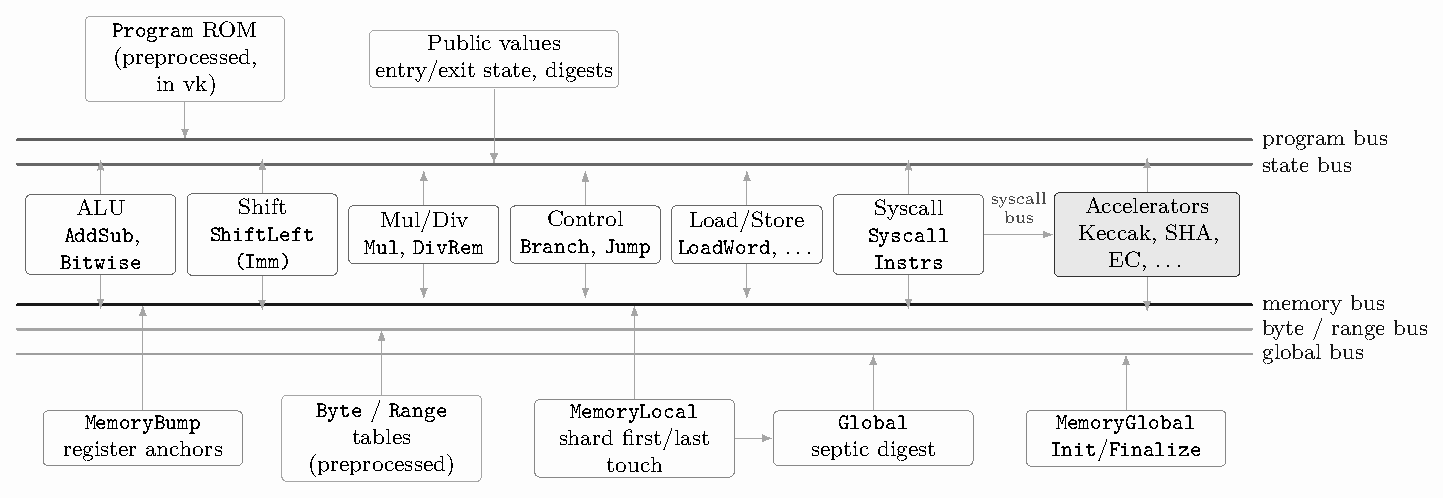
Figure 3 shows instruction chips connected by buses to a program ROM, a memory subsystem and lookup tables. A chip (Definition 2.4) is a fixed-width table over \mathbb{F} whose constraints, of degree at most three, are local to one row; every relation between chips, or between rows of one chip, is an interaction on a named bus, and the lookup argument of Section 5.6 proves that every bus balances (Definition 2.5). No constraint reads the next row: the state bus carries everything one row passes to the next. The trace area is the sum over chips of rows × columns. The guest-accelerator set is a configuration choice: it fixes which precompile chips a shard may contain, and adding one changes the chip set and the verifying keys. This section builds the parts every chip shares and what one row costs (§§5.1–5.8), then gives the chips instruction by instruction, for the base instruction set (§5.9) and for the extended instruction set and system calls (§5.10).
Appendix A catalogues the chips with their widths. Three families dominate the trace area of an Ethereum block: the memory-instruction chips, the ALU chips, and the Global chip that carries the cross-shard memory argument. Immediate forms of the ALU instructions have chips of their own, whose rows have one register read fewer and are about a tenth narrower.
Notation for words. A 32-bit word x is carried as four byte columns (x_0,x_1,x_2,x_3), least significant first, and denotes the integer \mathrm{int}(x)=\sum_{i<4}2^{8i}x_i; since 2^{32}>p that integer is never formed as a single field element. Its sign bit x_s is the top bit of x_3, and x_{<s} is the word with that bit cleared. A byte-checked word is one whose four columns are each proved to lie in [0,256) by the byte table. Signed instructions read a word in two’s complement, \mathrm{int}(x)-2^{32}x_s.
Lemma 5.1 (Limbs determine integers). Let x_0,\ldots,x_{\ell-1} be field elements proved to lie in [0,2^{b_i}) and let y\in[0,B), with 2^{b_0+\cdots+b_{\ell-1}}\le p and B\le p. If \sum_i 2^{b_0+\cdots+b_{i-1}}x_i=y holds in \mathbb{F}, it holds over the integers, and the x_i are the unique such limbs of y.
Proof. Both sides are integers in [0,p) that agree modulo p, so they are equal; uniqueness is that of positional notation. ∎
This is Cairo’s instruction-decoding theorem [GPR21, Thm. 1] in general form, and every word-level constraint of the machine must meet its hypothesis. A four-byte word cannot, since 2^{32}>p, so words stay as bytes. Two 16-bit half-words checked only against their sum in \mathbb{F} fail it for the same reason, which is why the syscall bus carries the half-words themselves (§5.10).
Padding. Row counts are rounded up to a multiple of 32, not to a power of two; the jagged commitment of Section 6 makes padding cost proportional to the padding. Padding rows have \mathsf{is\_real}=0, and every constraint and interaction multiplicity is gated so that they are vacuous.
The byte table has 2^{16} rows indexed by a byte pair and one multiplicity column per operation (bitwise operations, shifts, comparisons and 8/16-bit range checks); every carry, borrow, comparison and range check in the machine is an interaction with it. A range table serves the clock limbs, and the program table holds the decoded program image. Preprocessed tables are committed at setup as part of the verifying key, which therefore binds the image; OpenVM instead commits the program as a cached trace bound at the root of its recursion, so its verifying key is program-independent [Ope26b, §4.4].
The byte table as a decomposed instruction table. One lookup into the 2^{64}-entry table of a 32-bit bitwise operation becomes four lookups into the 2^{16}-entry byte table, indexed by a byte pair: the decomposition the original Jolt design applies to instruction tables through Lasso [AST24, STW24], taken at W=32 with four 8-bit chunks. Two things separate the settings. Lasso never commits its subtables, because the verifier evaluates their multilinear extensions itself [STW24]; a 2^{16}-row table is small enough to commit once in the verifying key, and LogUp-GKR then charges the table side one multiplicity column per operation over 2^{16} rows per shard, about 6.6\cdot10^5 cells, under 0.2% of a shard’s 4.6\cdot10^8-cell area budget (§4.2). And Jolt routes every instruction through such tables, addition and multiplication included; this arithmetisation evaluates those by constraints with byte-checked carries and uses the table only for byte-granular facts (§§5.9 and 5.10).
A conventional zkVM arithmetisation has a central CPU chip: one row per cycle fetches the instruction, performs the register accesses, chains the program counter and forwards a decoded instruction to an opcode chip, which spends a second row on it. Like SP1 and OpenVM for RISC-V [Suc24, Ope26b], Ziren has no such table. Each instruction chip embeds an instruction frame and performs those duties itself, so one executed instruction is one row of one chip. We call it a frame because it is the part of a row that is the same for every instruction and encloses the part that is not: whatever an opcode computes, its row sits inside a frame that says which instruction it is, when it ran, which registers it read and wrote, and which state it received and passed on. A chip’s own columns then only have to relate the frame’s operand values to its result. The name has nothing to do with a stack frame. The frame consists of:
HI. They use the register variant of the memory argument (§5.4). An \mathsf{op\_a\_0} flag pins a write to register 0 to zero, so chips bind their result through a (1-\mathsf{op\_a\_0}) factor.Lemma 5.2 (State-bus chain). In a valid shard (Definition 2.6) with entry state s_0 and exit state s_N, the real instruction rows can be ordered r_1,\ldots,r_N so that r_i receives s_{i-1} and sends s_i, with \mathsf{clk}(s_i)>\mathsf{clk}(s_{i-1}); every real instruction row is in the chain, and N is the number of real instruction rows.
Proof. Each real instruction row receives exactly one state tuple and sends exactly one, with a strictly larger clock, and the public-values table sends s_0 and receives s_N. Balance of the state bus means the multiset of sent tuples equals the multiset of received tuples. Consider the directed graph whose vertices are the distinct state tuples and whose edges are the rows (from received tuple to sent tuple). Every vertex other than s_0 and s_N has in-degree equal to out-degree, s_0 has out-degree one more than in-degree and s_N the reverse, so the edge multiset decomposes into one s_0\to s_N path and cycles. A cycle is impossible because the clock strictly increases along every edge. Hence the rows form a single path from s_0 to s_N. ∎
Figure 4 shows three consecutive rows and the buses that bind them. The frame comes in R-type (two register reads), I-type (a word immediate, used by the immediate ALU, memory and branch chips) and shift-amount (a 5-bit immediate) variants, and a universal variant for chips whose opcodes mix operand shapes. It byte-checks the word written to \mathsf{op\_a}, the single place where a register value is range-checked, which lets memory-instruction rows omit byte checks on the words they move.
Example 5.3 (A delay slot on the state bus). Take a taken beq at address 0x100 whose target is 0x200, the addiu in its delay slot at 0x104, and the instruction at the target. With the shard s and the branch’s clock \mathsf{clk}, the three rows exchange these tuples on the state bus:
| Row | Chip | receives (\mathsf{shard},\mathsf{clk},\mathsf{pc},\mathsf{next\_pc}) | sends |
|---|---|---|---|
beq |
Branch |
(s,\mathsf{clk},\texttt{0x100},\texttt{0x104}) | (s,\mathsf{clk}+5,\texttt{0x104},\texttt{0x200}) |
addiu |
AddSubImm |
(s,\mathsf{clk}+5,\texttt{0x104},\texttt{0x200}) | (s,\mathsf{clk}+10,\texttt{0x200},\texttt{0x204}) |
| target | any | (s,\mathsf{clk}+10,\texttt{0x200},\texttt{0x204}) | (s,\mathsf{clk}+15,\texttt{0x204},\ldots) |
The branch does not change its own successor, 0x104; it sets the one after it. The addiu row is an ordinary row that happens to receive \mathsf{next\_pc}=\texttt{0x200} and sends (\texttt{0x200},\texttt{0x204}) by the constraint every sequential row obeys. Not taken, the branch would have sent (\texttt{0x104},\texttt{0x108}) and nothing else would change. The pair crosses a shard boundary whole, so the recursion must pin both components (§8), and a shard is never cut between a transfer and its delay slot.
The frame beside other instruction interfaces. SP1 gives each instruction chip a column group that chains (\mathsf{clk},\mathsf{pc}) and an R-, I- or J-type register reader that fetches the instruction and reads its operands [Suc24]; the frame’s R-type, I-type and shift-amount variants correspond to those readers. OpenVM factors an instruction executor into an adapter, which owns every program, execution and memory interaction, and a core, which computes [Ope26b]. The frame fills the same role for MIPS32. It differs from both in carrying the delay slot, and from OpenVM in four respects. The state is (\mathsf{shard},\mathsf{clk},\mathsf{pc},\mathsf{next\_pc}) rather than (\mathsf{pc},t), because of the delay slot. Time advances by a fixed five per instruction with a fixed position per access, where OpenVM advances one tick per access; in both, the accesses of step i sit strictly between the states received and sent,
\mathsf{clk}_i<\mathsf{clk}_i+1<\mathsf{clk}_i+2<\mathsf{clk}_i+3<\mathsf{clk}_i+4<\mathsf{clk}_{i+1}=\mathsf{clk}_i+5,
with the memory access at \mathsf{clk}_i itself. Registers are shadow-read into the shard and use a six-column access (§5.4), where OpenVM’s are ordinary memory in a separate address space. And OpenVM’s connector chip is here the public-values table.
Both designs state their buses by the same kind of invariant: (\mathsf{shard},\mathsf{clk},\mathsf{pc},\mathsf{next\_pc}) is sent on the state bus exactly when it is the machine state at that clock, and (\mathsf{shard},\mathsf{clk},a,v) is on the memory bus exactly when address a held v after its access at that time.
The frame as a reordering of the trace. A per-step circuit that can execute any instruction must either contain every instruction’s logic at every step or be told which one runs. vRAM [ZGK+18] took the second route: the prover announces how often each instruction executed, commits the trace regrouped by instruction, and proves by a permutation check that it is a reordering of a time-ordered trace; Jolt names the same device as one way to route its lookups by opcode [AST24], and Ceno’s per-opcode design gives it in multiset form, as a set equality over (program counter, clock) state records [LZZ+24, §6.2]. The frame realises this regrouping with a program-counter pair and a shard field in the state. The chips are the groups, their heights are the instruction counts and enter the transcript before any challenge, and the state bus is the permutation check: Lemma 5.2 says the grouped rows re-assemble into one time-ordered chain. The regrouping is of instructions only; the memory argument below does not reorder the trace, which makes it reordering-free in the taxonomy of Twist and Shout [ST25, App. A].
The price of the regrouping is uniformity. A circuit that carries every instruction at every step has a trace shape that depends only on its length, as RISC Zero’s does [BGt23], or on its length and configured builtins, as Cairo’s does [GPR21, §2.8], which makes Cairo’s verifier program-independent and its recursion simple [GPR21, §2.2.4]. Here the shape depends on which counts are non-zero, so the key of the program that verifies a shard is a function of its chip set, and Section 8 enumerates those sets.
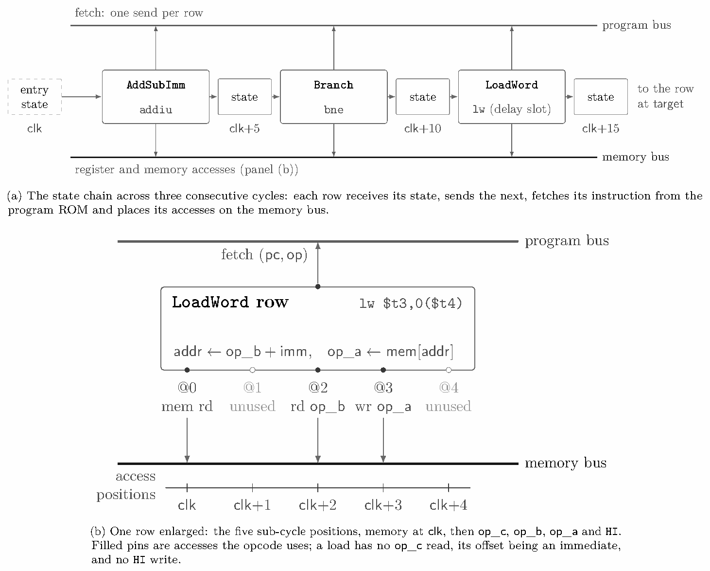
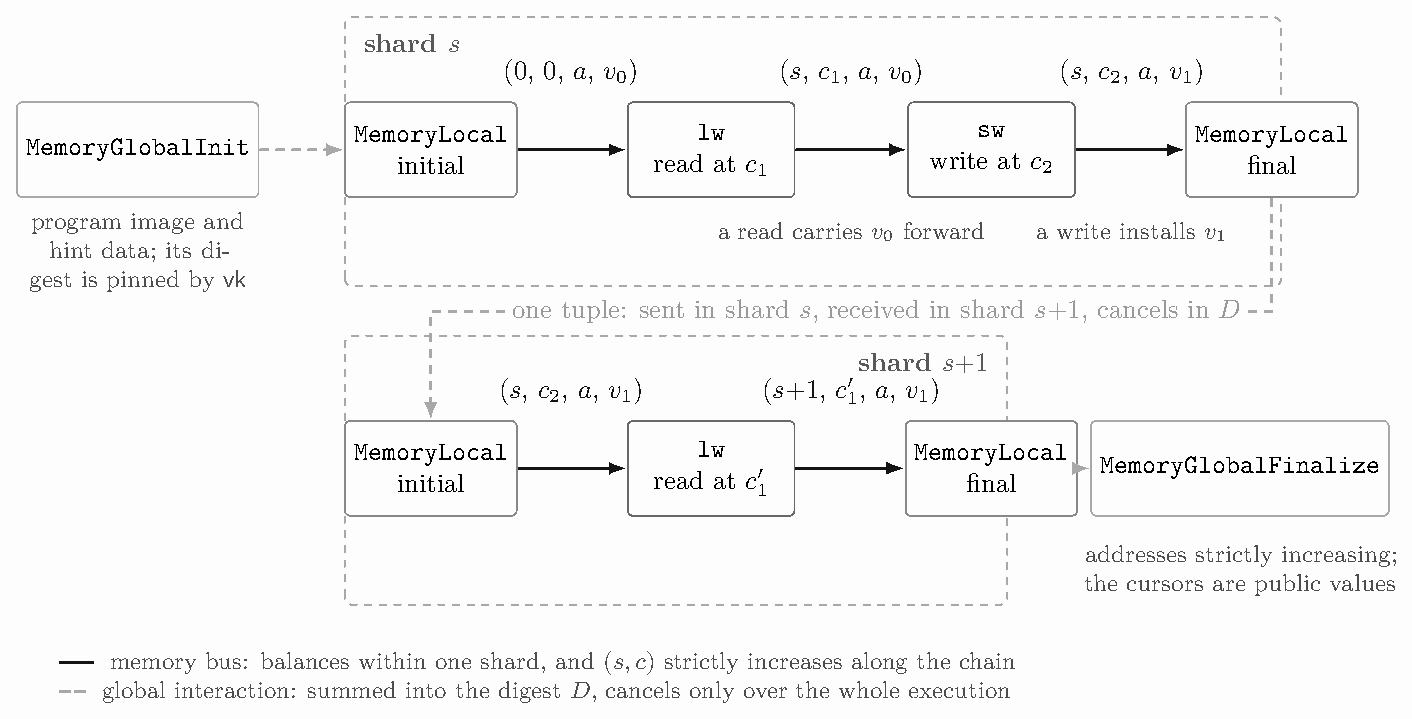
LoadWord row sits in the branch’s delay slot, so its successor arrives as the branch target rather than \mathsf{pc}+4; the rows are an AddSubImm, a Branch computing \mathit{taken}\leftarrow[a\ne b] on registers rs and rt, and the aligned four-lane load of panel b.Registers and memory share one offline memory-checking argument [BEG+94] in the multiset style used by SP1 [Suc24]. The state of address a is the tuple (\mathsf{shard},\mathsf{clk},a,\mathsf{value}) of its last access. An access at time (s,c) sends the previous tuple (s',c',a,v') and receives the new tuple (s,c,a,v) on the memory bus, with v=v' for a read. Every access enforces (s',c')<(s,c) by witnessing c-c'-1, or s-s'-1 when the shards differ (a one-bit \mathsf{compare\_clk} selector chooses), as a range-checked 16-bit limb and 10-bit high limb, which covers a \mathsf{clk}+\mathsf{pos} timestamp under the 25-bit clock fence. Words are carried as four byte columns. Figure 5 follows one address through two shards.
Lemma 5.4 (Memory argument). The memory bus with the timestamp constraints is a memory-checking argument in the sense of Definition 2.3, up to the fingerprinting error of the bus argument and provided the bus’s multiplicities satisfy the bound of Definition 2.5. Concretely, in a valid shard with at most one initial-state row and one final-state row per address, for every address a the accesses to a form a chain ordered by (\mathsf{shard},\mathsf{clk}) in which each access consumes exactly the tuple produced by the previous access to a, starting from the tuple supplied by the initial-state row of a and ending at the tuple consumed by its final-state row; in particular every read returns the value of the last write.
Proof. Each access sends its previous tuple and receives its new tuple on the memory bus, and its constraints enforce that the new timestamp strictly exceeds the previous one. Balance of the memory bus, restricted to the tuples with address a, gives a graph as in Lemma 5.2 with the initial-state row as source and the final-state row as sink; strictly increasing timestamps exclude cycles, so the accesses form one path, and along the path a read carries its previous value forward unchanged. ∎
Registers. A dedicated chip, MemoryBump, inserts, for every register at its first touch in a shard, a shadow read at (\mathsf{shard},0), a device SP1 introduced [Suc24]. Since \mathsf{clk} restarts at zero in every shard and real register accesses sit at positions 1..4, the previous access of a register is always in the current shard. The register variant of the access columns therefore drops \mathsf{prev\_shard}, the compare selector and one limb, re-derived linearly from the others: 9 columns become 6 on every register access.
Shard-local memory. Within a shard, the first access to a word consumes a tuple no access in the shard produced, and the last produces one nothing in the shard consumes. A shard-boundary chip, MemoryLocal, records, for every word the shard touches, its initial and final (\mathsf{shard},\mathsf{clk},\mathsf{value}); it receives the initial tuple on the memory bus, sends the final one, and forwards both as global interactions (§5.5) to be matched across shards. A shard of an Ethereum block executed by the reth client touches a few hundred thousand words, mostly a hot working set touched again in the next shard, and these two global rows per touched word are among the largest contributions to trace area, which is why shard size matters (Section 10).
Whole-execution memory. Two further chips, MemoryGlobalInit and MemoryGlobalFinalize, carry the memory’s initial contents (the program image and the hint data written into untouched words) and its final contents; an initial tuple carries timestamp (0,0), below every access. Both witness the word as 32 boolean columns, so every value that enters memory is byte-shaped by construction. Only words the execution touches appear, as in Ceno [LZZ+24, §5.1]. Addresses are 32-bit decomposed and proved strictly increasing along the table, and the address cursors are public values, so the recursion checks that consecutive tables tile the address space. The program image is bound by the verifying key: its digest (§5.5) is a public parameter the init table must consume.
What is byte-checked. Every value that enters a register is byte-checked by the frame at the write, and every value a precompile writes to memory is byte-checked or bit-decomposed by the precompile chip; memory-instruction rows therefore omit the two byte lookups per word that accesses otherwise carry.
Why not Twist. Twist and Shout [ST25] checks memory with one-hot addresses and increments far more cheaply than timestamped checking, but its costs assume commitments in which zeros are free or bits pack, and it notes that committing to zeros is not free under a hash-based commitment [ST25, §2.9]: a one-hot register address alone would be 32 cells against the six of a register access here. Across shards, Twist must commit the memory’s state at each boundary, which it leaves open [ST25, §2.9]; the digest below pays only for the words a shard touches.
Interactions whose two sides live in different shards (the initial and final tuples of every shard-touched word, memory initialisation and finalisation, and syscall pairings) cannot be balanced by a per-shard fraction sum. Each shard proof therefore publishes a commitment to its cross-shard state, and the recursion checks that the commitments of the shards compose; the per-shard argument is the same whatever that commitment is. There are four options: two multiset hashes, over an elliptic curve and over a lattice, a global challenge, and Merkle roots over touched memory. They differ in what a shard publishes, what composition checks and what soundness rests on, and they trade committed area against the order in which shards can be proved (Table 3); three are implemented and measured, and the lattice hash is costed. The choice among them is a practical one. The measurements of Section 10 and the soundness accounting of Section 9 are stated for the elliptic-curve multiset hash.
Option 1: elliptic-curve multiset hash. Each interaction tuple is mapped into a commutative group, sends add its image and receives subtract it, each shard publishes its running sum, its cross-shard digest D, and the root compose node checks that the sums over the execution add to the identity: the multiset hash of Clarke et al. [CDvD+03] on the incremental hashing of Bellare and Micciancio [BM97]. On an elliptic curve [MSTA17], which SP1 introduced to zkVM memory checking [RR24], a tuple \boldsymbol m\in\mathbb{F}^7 is lifted to a point of E: y^2=x^3+3\zeta x-3 over \mathbb{F}_{p^7}=\mathbb{F}[\zeta]/(\zeta^7+2\zeta-8). One row per interaction witnesses the point, checks the curve equation and a sign band for y that separates sends from receives, and adds the point to a running sum on an accumulation bus; the sum starts at a public offset point D_{\mathrm{off}}, so two digests combine as D+D'-D_{\mathrm{off}} and the empty digest is D_{\mathrm{off}}. The lift applies no hash: the message is the x-coordinate, up to a prover-chosen byte offset that makes the curve’s right-hand side a square, which keeps the chip at a few dozen columns; §9.5 gives what soundness then rests on.
Option 2: lattice multiset hash. The group can instead be a lattice, as in LtHash [LKMW19], the instantiation of Bellare and Micciancio’s incremental hash over a product of small rings, which ZisK uses for its challenge derivation [Mas25]. A tuple \boldsymbol m is hashed to h(\boldsymbol m)\in\mathbb{F}^n, sends add h(\boldsymbol m) and receives subtract it, each shard publishes its running sum, and composition checks that the sums over the execution add to zero, exactly as for the curve. A collision is a short integer relation among hash outputs, a problem not known to be easy for quantum adversaries. The cost is h: it must be constrained in the chip for every interaction, and it must behave as a random function, since a linear h makes any two multisets with equal message sums collide, which is what our prototype with a fixed public linear map did. A map strong enough for the lattice assumption needs n=800 or more over the 31-bit field and at least 19.6× today’s committed area by our count, so this option is costed, not built.
Table 3: The four options for cross-shard interactions. Times are relative to the elliptic-curve multiset hash on the same GPUs (warm, compressed proofs, \mathsf{H}= Poseidon2); the global challenge was measured on one block, Merkle roots over six and twelve blocks with the two builds alternated (ABBA), the block count in parentheses. The lattice multiset hash is estimated, not built.
| Option | a shard publishes | composition checks | soundness rests on | 1 GPU | 4 GPUs | other costs |
|---|---|---|---|---|---|---|
| 1. Elliptic-curve multiset hash | a running sum of points | the sums add to the identity | Assumption 9.4 | – | – | |
| 2. Lattice multiset hash | a running sum of vectors | the sums add to zero | short integer relations | ≥ 19.6× area | not built | |
| 3. Global challenge | a LogUp-GKR fraction sum | the sums add to zero | the hash chain, LogUp-GKR | +29 % | +42 % | a commit pass before proving |
| 4. Merkle roots | memory roots before and after | the roots chain from the image root | collision resistance of \mathsf{H} | −16.6 % (6) | +3.4 % (12) | −47 % shards; +20 GB per worker |
Option 3: global challenge. Every shard commits its main trace first; one LogUp-GKR challenge is then drawn from a hash chain over all the commitments, each shard proves its cross-shard interactions as LogUp-GKR fractions under that challenge and publishes their sum, and the recursion checks that the sums over the execution add to zero. Soundness rests on the hash chain and on the LogUp-GKR argument the shards already use, and the option adds no hashing to the machine. The price is order: every shard must be committed before any can be proved, which on the GPU pipeline means a commit pass ahead of the proving pass.
Option 4: Merkle roots over touched memory. Memory is a Merkle tree under \mathsf{H}, a height-27 tree of four-word leaves and a height-4 tree of registers joined under one root, and each shard publishes the root before it and the root after it. A boundary unit recomputes, for every leaf the shard touches, its path in the initial tree and in the final tree: it sends the leaf’s initial words on the memory bus and receives its final words, so the shard’s accesses balance inside the shard, and the untouched siblings along the paths enter both trees through one lookup. A per-word initialisation bit replaces the initialisation table, and precompile and syscall pairings balance in the shard that issues them, the executor closing a shard before a precompile that would give its recursion leaf an area no recursion shape admits. Composition checks that each shard’s outgoing root is the next shard’s incoming root and that the first is the image root the verifying key fixes. Soundness rests only on the collision resistance of \mathsf{H}; the accumulation rows and cross-shard memory units leave the machine, the Merkle rows take their place, and every measured block proves through compression with the root chain closed.
One LogUp-GKR instance, the bus argument, proves all interactions of a shard on the program, state, memory, byte, range, syscall, global and accumulation buses. After the trace is committed, the verifier samples \alpha,\beta\in\mathbb{F}_{p^4}; every interaction (\mathsf{bus},\boldsymbol f,m) contributes m/\big(\alpha-\mathsf{bus}-\sum_{j\ge1}\beta^j f_j\big), and the prover shows that sends and receives have equal sums. The fractions are the leaves of a layered GKR circuit whose transitions sumcheck proves from the root down, and the final layer leaves evaluation claims on the participating columns. A reth shard has on the order of 10^8 leaves, one per (row, interaction) pair, so interactions per row cost separately from columns, and this circuit is the largest GPU-kernel consumer (Section 10). Its soundness is \deg/|\mathbb{F}_{p^4}| per sumcheck round plus the fingerprint’s collision probability, which grows with the number of leaves (§9.2); the schedule of Table 5 grinds the LogUp-GKR challenge by 22 bits.
The constraint system is uniform: a chip imposes the same constraints on every row, so nothing about it is committed and the verifier evaluates the constraint polynomials itself at the closing point. All chips’ constraints are proved by one zerocheck. The verifier samples \eta to combine chips and \mu to combine a chip’s constraints, so that C_c(\boldsymbol X)=\sum_k\mu^k c_{c,k}(\mathrm{row}(\boldsymbol X)) must vanish on chip c’s real rows, and the prover proves \sum_{\boldsymbol b}\mathrm{eq}(\boldsymbol b,\boldsymbol r)\sum_c\eta^c C_c(\boldsymbol b)=0 for a random \boldsymbol r by sumcheck over the tallest chip’s variables, with shorter chips handled by an analytic “virtual ≥” factor rather than padding. Constraint degree three gives round polynomials of degree four. The GPU’s constraint kernels are compiled per chip from the description the verifier uses, except for the widest accelerator chips, which are interpreted (Table 9), and host verification catches any mismatch. The zerocheck is seeded from the LogUp-GKR openings, so the two share one opening of each column; what remains is about 3.6\cdot10^4 (chip, column, point, value) claims per shard, which the commitment layer reduces to one.
Counting a step’s committed elements shows that an instruction’s cost lies in the state its row reads and writes, not in the function it computes. The R-type frame is 30 columns: eight for the shard, the two clock limbs, the opcode, the three register indices and the zero-register flag, and 22 for the three register accesses (ten for the read–write of \mathsf{op\_a}, its previous word plus six access columns, and six per read). The I-type frame is 27 columns and the shift-amount frame 24. With the program-counter pair each chip owns, an instruction pays 32 columns before it computes anything; Bitwise then adds five and AddSub four. The register memory check is therefore most of every common row, and the six-column register access saves three columns on every access of every instruction. §§5.9 and 5.10 report each chip against this floor, and Section 10.2 turns the widths into a cost per executed instruction.
For each instruction family we give the chip, its frame, how the row fixes the result, and the lookups the chip adds to its frame’s. Operands follow Definition 4.2: a is the word written to (or, for stores and branches, read from) register \mathsf{op\_a}, and b and c are the words of \mathsf{op\_b} and \mathsf{op\_c}, from registers or decoded immediates, in the notation of §5.1. Every result is gated by (1-\mathsf{op\_a\_0}), which the tables omit.
Frames. The frame’s interactions are paid on every row (§5.3): 20 for the R-type frame and 16 for the I-type and shift-amount frames, itemised in Appendix A. A universal frame, for chips whose opcodes mix operand shapes, is the R-type frame with its reads gated by the immediate flags. The four frames play the part of OpenVM’s six RV32IM adapters [Ope26b]; loads, stores and branches share the I-type frame. Widths are from Table 12, and lookups are counted beyond the frame’s.
| Instructions | Chip (width), frame | Result | Added lookups |
|---|---|---|---|
and, or, xor, nor |
Bitwise (37), R |
a_i=\mathrm{OP}(b_i,c_i), i<4 | 4 byte-table |
andi, ori, xori |
BitwiseImm (33), I |
a_i=\mathrm{OP}(b_i,c_i), i<4 | 4 byte-table |
A bitwise operation has no constraint at all: each byte pair is one lookup into the byte table, whose operation index is a selector-weighted sum of the opcode flags (§5.2). The immediates of andi, ori and xori are zero-extended at decode, and nor has no immediate form.
| Instructions | Chip (width), frame | Result | Added lookups |
|---|---|---|---|
add, addu |
AddSub (36), R |
a=b+c \bmod 2^{32} | none |
sub, subu |
AddSub (36), R |
a+c=b \bmod 2^{32} | none |
addi, addiu |
AddSubImm (33), I |
a=b+\mathrm{sext}(\mathit{imm}) \bmod 2^{32} | none |
lui |
AddSubImm (33), I |
a=0+(\mathit{imm}\ll 16) | none |
mfhi, mflo, mthi, mtlo |
AddSubImm (33), I |
a=b+0 | none |
Addition is checked byte by byte with carries that are not columns: the carry out of byte i is the linear expression \theta_i=(b_i+c_i-a_i+\theta_{i-1})/256, \theta_{-1}=0, and the chip asserts \theta_i(\theta_i-1)=0; subtraction asserts the same of a+c=b. The frame byte-checks the result, so the family adds four columns (two selectors, two gates) and no lookup. Jolt instead forms b+c as one element of a 256-bit field and looks up its low bits [AST24], which 2^{32}>p rules out here. lui adds an immediate shifted at decode to register 0, and the moves between HI (register 33), LO (register 32) and the general registers add zero. add and addi decode exactly as addu and addiu: the manual’s overflow trap is modelled by neither the executor nor the chip (§4.3).
| Instructions | Chip (width), frame | Result | Added lookups |
|---|---|---|---|
sltu, slt |
Lt (50), R |
a=x_s(1-y_s)+\mathrm{eq}(x_s,y_s)\,\mathrm{LTU}(x_{<s},y_{<s}) | 2 AND, 1 LTU |
sltiu, slti |
LtImm (47), I |
as above, y=\mathrm{sext}(\mathit{imm}) | 2 AND, 1 LTU |
With x=b and y=c the result is Jolt’s signed less-than, while for the unsigned forms the sign bits are not split off and LTU compares the full words [AST24]. Two AND lookups clear the top bit of each high byte, which gives x_{<s}, y_{<s} and, by difference, the sign bits. The unsigned part is decomposed differently: Jolt sums over chunks, weighting each chunk’s less-than by the equality of every chunk above it, a less-than and an equality lookup per chunk; Lt witnesses a one-hot flag for the most significant differing byte, asserts by constraints that the bytes above it agree and, through a witnessed inverse, that the flagged bytes differ, and spends one LTU lookup on the flagged pair. The upper three result bytes are zero.
| Instructions | Chip (width), frame | Result | Added lookups |
|---|---|---|---|
sll |
ShiftLeftImm (45), shift |
a=b\cdot2^k \bmod 2^{32}, k=\mathit{sa} | 4 range |
sllv |
ShiftLeft (62), R |
a=b\cdot2^k \bmod 2^{32}, k=c \bmod 32 | 4 range |
srl, sra, rotr |
ShiftRightImm (83), shift |
low word of (\hat b\gg k), k=\mathit{sa} | 1 MSB, 8 ShrCarry, 16 range |
srlv, srav, rotrv |
ShiftRight (89), R |
low word of (\hat b\gg k), k=c \bmod 32 | 1 MSB, 8 ShrCarry, 16 range |
A shift by k=8q+r is a shift by r bits followed by a relabelling of whole bytes by q. The shift amount is decomposed into bits, of which the low five are used (the manual’s reduction modulo 32), and one-hot selectors for q\in[0,4) and r\in[0,8) are tied to them. A left shift multiplies by 2^r with witnessed per-byte carries, \rho_i=2^r b_i+\theta_{i-1}-256\theta_i, then moves byte i to byte i+q; the shift-amount form computes 2^r as (1+s_0)(1+3s_1)(1+15s_2) with no one-hot. A right shift first extends b to eight bytes \hat b, whose upper four are zero for srl, 0xFF times the sign bit for sra, and a copy of b for rotr, so one right shift leaves the rotation in the low half. The bit part uses eight ShrCarry lookups, each mapping a byte and a 3-bit shift to the shifted byte and the bits shifted out: Jolt’s shift decomposition [AST24], a subtable indexed by a chunk and the shift amount, with the byte part done by relabelling.
| Instructions | Chip (width), frame | \mathsf{next\_next\_pc} | Added lookups |
|---|---|---|---|
beq, bne |
Branch (56), I |
\mathsf{next\_pc}+\mathit{off} if taken, else \mathsf{next\_pc}+4 | ≤ 9 of 13 |
bgez, bgtz, blez, bltz |
Branch (56), I |
as above, comparing with register 0 | ≤ 9 of 13 |
j, jal |
Jump (57), universal |
\mathit{target}\ll 2 | 3 LTU |
jr, jalr |
Jump (57), universal |
b | 3 LTU |
bal |
Jump (57), universal |
\mathsf{next\_pc}+\mathit{off} | 3 LTU, 6 range |
A transfer does not change \mathsf{next\_pc}, the address of its delay slot; it sets \mathsf{next\_next\_pc}, the second component of the pair it sends, and the delay-slot instruction is simply the next row of the chain (Example 5.3). Branch compares a (register rs) with b (register rt, or register 0 for the compare-with-zero forms). Equality is two is-zero tests, by witnessed inverses, on the differences of the 16-bit halves; the sign of a is one MSB lookup, gated to the compare-with-zero forms; and a>0 is (1-a_s)(1-[a=0]). The offset is shifted and sign-extended at decode, so the taken target is one in-row addition with a byte-checked result, and one LTU lookup per counter word proves it canonical. Jump writes the link \mathsf{next\_pc}+4, which is \mathsf{pc}+8 through the chain, and takes its target from the immediate, from register b, or from an addition for bal. The region bits that j and jal take from the program counter in the manual are zero in both the executor and the chip, which is exact for text below 2^{28}, where the guest toolchain links it.
| Instructions | Chip (width), frame | Result | Added interactions |
|---|---|---|---|
lw, ll |
LoadWord (48), I |
a=M[\mathit{addr}] | 9 |
sw, sc |
StoreWord (52), I |
M[\mathit{addr}]\leftarrow a; sc also sets a=1 |
9 |
lb, lbu, lh, lhu |
LoadNarrow (59), I |
selected byte or half, sign- or zero-extended | 10 |
sb, sh |
StoreNarrow (55), I |
byte or half of a merged into M[\mathit{addr}] | 9 |
lwl, lwr, swl, swr |
MemoryUnaligned (59), I |
byte-wise merge of M[\mathit{addr}] and a | 9 |
The five memory chips share one block of columns and nine interactions. The effective address b+\mathrm{sext}(\mathit{off}) is one in-row addition with range-checked result bytes; one LTU proves it canonical and a second, with an is-zero test on its upper bytes, that it lies above the 36 register addresses; and one AND lookup extracts its two low bits, from which the aligned address is linear. The access is one word-granular access at sub-cycle position 0 (two memory-bus interactions and two timestamp lookups), and the word is not byte-checked again, since every value that enters memory is byte-shaped at its source (§5.4). The word forms assert that the low bits are zero; the narrow and unaligned forms turn them into one-hot offset flags and select or merge bytes polynomially, and a narrow signed load adds one MSB lookup and fills with 0xFF times the bit. For a single-threaded guest, ll is lw with no reservation, and sc always succeeds and writes 1.
OpenVM likewise accesses aligned four-cell blocks and selects bytes within the row [Ope26b, §3.2.4], where the original Jolt design spends one memory-checking operation per byte [AST24]; the price is the offset flags and merge columns that make the narrow and unaligned chips the widest of the family.
Each of these instructions is still one row of one chip, which carries as columns the work a lookup-based design spreads over a sequence of virtual instructions [AST24], and HI (register 33) is written by a second access at sub-cycle position 4. That access raises eight interactions, counted as “an access” in the tables below: a send and a receive on the memory bus, two timestamp lookups, and two byte lookups each for its previous and its new word.
| Instructions | Chip (width), frame | Result | Added lookups |
|---|---|---|---|
mul |
Mul (74), R |
a=b\cdot c \bmod 2^{32} | 14, and an access |
mult, multu |
Mul (74), R |
(\texttt{HI},\texttt{LO})=b\cdot c, signed or unsigned | 14, and an access |
madd, maddu, msub, msubu |
MiscInstrs (432), universal |
(\texttt{HI},\texttt{LO})\mathrel{\pm}=b\cdot c | 26, and an access |
A 64-bit product exceeds the field, so it is formed as a convolution of bytes. Both operands are extended to eight bytes, with 0xFF times the sign bit for the signed forms mult, madd and msub (two MSB lookups) and zeros otherwise; the sign extension does in the row what Jolt’s virtual sequence for signed high multiplication does [AST24]. The uncarried convolution m_k=\sum_{i+j=k}b_ic_j, k<8, is tied to witnessed product bytes \pi_k and carries \theta_k by m_k+\theta_{k-1}=\pi_k+256\,\theta_k, with carries range-checked to 16 bits and product bytes to 8. The low word \pi_{0..3} goes to \mathsf{op\_a} (LO for mult and multu, rd for mul) and the high word to HI. The multiply–accumulate forms add the same product to the 64-bit (\texttt{HI},\texttt{LO}) with a byte-carry addition, and prove a subtraction as the addition that undoes it.
| Instructions | Chip (width), frame | Result | Added lookups |
|---|---|---|---|
div, divu |
DivRem (163), R |
\texttt{LO}=q, \texttt{HI}=r with b=qc+r, \lvert r\rvert<\lvert c\rvert | 36, and an access |
As in Jolt [AST24], the prover supplies the quotient q and remainder r as advice and the row checks them; Jolt’s check is eight virtual instructions; here it is 131 columns beyond the frame. qc is formed by the Mul convolution, signed for div, and r, sign-extended to eight bytes, is added with byte carries; the low word of the sum must equal b and the high word its sign extension. The remainder takes the dividend’s sign, and |r|<|c| compares absolute values, each proved by an addition to zero when negative, with the one-flag comparison of Lt. The overflowing case b=-2^{31}, c=-1 is detected by two word-equality tests and exempts the high word. Division by zero is an execution error (§4.3), and the row asserts c\ne0.
| Instructions | Chip (width), frame | Result | Added lookups |
|---|---|---|---|
clz, clo |
CloClz (93), I |
leading zeros of b, or of \neg b | 28 |
movz, movn |
MovCond (49), universal |
a=b if [c=0] (resp. \ne), else a unchanged | none |
wsbh |
MovCond (49), universal |
a=(b_1,b_0,b_3,b_2) | none |
seb, seh |
MiscInstrs (432), universal |
b_0 or (b_0,b_1), sign-extended | 1 MSB |
ext, ins |
MiscInstrs (432), universal |
bit-field extract, insert | up to 113 |
teq |
MiscInstrs (432), universal |
no trap: a\ne b | none |
clo is clz of the complemented word. For clz, the zero word yields 32; otherwise the row proves, with the right-shift construction of §5.9.4 inlined, that shifting b right by 31-a leaves exactly 1, and an LTU lookup bounds a by 32. The conditional moves test c=0 by two witnessed inverses on its 16-bit halves and select between b and the previous value of \mathsf{op\_a}, which the frame’s read–write access carries; wsbh is a byte permutation. ext is a left shift followed by a right shift, and ins rotates the destination, shifts, adds the shifted source and rotates back. These rare opcodes share MiscInstrs, whose opcode-specific columns overlap in a union, so the row is as wide as ins and every lookup is gated by an opcode selector. teq is provable only when it does not trap.
| Instructions | Chip (width), frame | Effect | Added interactions |
|---|---|---|---|
syscall |
SyscallInstrs (68), R |
sends id, b, c as 16-bit halves | 2 LTU, 2 syscall-bus |
| Linux ABI calls | SysLinux (100), none |
brk, mmap, read, write, … |
up to 50, gated |
| accelerators | per precompile, none | a hash or curve operation in memory | per chip |
SYSCALL is the one place a row hands work to another table. The call number in $v0 is read as bytes: the low two are the call identifier, the third says whether the call is sent to a table, and the fourth is a count of extra clock ticks, by which the frame advances the clock beyond five so that a precompile’s memory accesses fit before the successor. The two arguments travel on the syscall bus as exact 16-bit halves with a Linux flag. A halting call sets the next program counter to zero and exposes its first argument as the public exit code; a commit call compares its argument with the public output digest. SysLinux receives the Linux-ABI calls and performs their memory accesses at the calling cycle, and the precompile chips of Appendix A receive accelerator calls, routed across shards through the digest or, with Merkle roots, proved in the shard that issues them (§5.5). The Jolt design [AST24] has no precompile tables; cryptographic operations there are compiled into sequences of ordinary and virtual instructions.
After the bus argument and the zerocheck of a shard (§§5.6 and 5.7), the verifier holds evaluation claims on individual chip columns: about 3.6\cdot10^4 per reth shard, with heights from 32 rows to millions. Committing each column or table separately costs one Merkle root and one query phase per commitment, and puts every table’s height into the verifier, so that each height profile needs a verifier circuit of its own [HJR+25, p. 4]. The jagged polynomial commitment of Hemo et al. [HJR+25] commits the non-zero part of all columns as one dense multilinear and reduces every column claim to one evaluation of it. Ziren uses its basic construction [HJR+25, Thm. 1.4] with its jagged assist [HJR+25, Thm. 1.5]; it uses neither the “fancy” variant for columns of equal height (§6 there) nor committed heights proved by GKR (§1.1.2 there), because the machine’s columns are too heterogeneous for grouping into power-of-two tables to pay.
Sections 6.1–6.3 restate the construction in our notation. Sections 6.4–6.6 describe what Ziren adds: several ordered commitments opened as one, the stacked layout of the opening, and a quantised geometry that makes the verifier a function of a small class rather than of a shard’s row counts. A chip can therefore be widened, added or removed without changing the layer above it; the chip revisions of §10.2 left this protocol unchanged. Figure 6 shows the construction end to end.
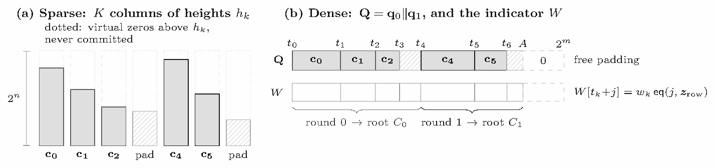
Let there be K columns \mathbf c_0,\ldots,\mathbf c_{K-1} with heights h_0,\ldots,h_{K-1}\le 2^n, viewed as one function p:\{0,1\}^n\times\{0,1\}^\kappa\to\mathbb{F}, \kappa=\lceil\log_2K\rceil, with p(x,k)=\mathbf c_k[x] for x<h_k and p(x,k)=0 otherwise. Such a function is jagged [HJR+25, Def. 1.1]. Its non-zero part is the dense representation
\mathbf Q=\mathbf c_0\,\|\,\mathbf c_1\,\|\cdots\|\,\mathbf c_{K-1},\qquad t_0=0,\quad t_{k+1}=t_k+h_k,\quad A=t_K,
padded with zeros to M=2^m, m=\lceil\log_2A\rceil, and written \widetilde Q as a multilinear in m variables. Column k occupies [t_k,t_{k+1}) in \mathbf Q, and the prefix sums are public: they enter the transcript before any challenge. \mathbf Q and the prefix sums determine p [HJR+25, Fact 1.3], so committing to \widetilde Q commits to every column at the cost of the real area A rather than K\cdot2^n.
Table 4: Notation of this section against that of Hemo et al. [HJR+25].
| Here | [HJR+25] | Meaning |
|---|---|---|
| K, \kappa=\lceil\log_2K\rceil | 2^k, k | number of columns |
| n, m, M=2^m | n, m, M | log height of the row cube; log and size of the dense domain |
| h_k, t_k (exclusive) | h_y, t_y (inclusive) | column heights and prefix sums |
| \mathbf Q, \widetilde Q | q, \widehat q | dense representation |
| W | f_t(z_r,z_c,\cdot) | the indicator of Equation (1) |
| \boldsymbol z_{\mathrm{row}}, \boldsymbol z_c, \boldsymbol z^* | z_r, z_c, i | row point, column point, dense point |
| \mathsf{BP}, u_k | \widehat g, (t_{y-1},t_y) | branching program and its boundary input |
Table 4 maps our notation to the paper’s. Two differences are inessential: our prefix sums are exclusive (t_k starts column k), and a boundary takes m+1 bits because t_K=A may equal 2^m. Heights may reach 2^n rather than 2^n-1, which is harmless because only boundaries are encoded.
Let \boldsymbol z_{\mathrm{row}}\in\mathbb{F}_{p^4}^n be the common row point left by the zerocheck, and y_k the claimed evaluation of column k there, high zeros included:
y_k=\sum_{j=0}^{h_k-1}Q[t_k+j]\,\mathrm{eq}(j,\boldsymbol z_{\mathrm{row}})=\widetilde p(\boldsymbol z_{\mathrm{row}},k).
The verifier samples a column point \boldsymbol z_c\in\mathbb{F}_{p^4}^\kappa, which turns the K claims into the single claim
T=\sum_{k<K}\mathrm{eq}(k,\boldsymbol z_c)\,y_k=\widetilde p(\boldsymbol z_{\mathrm{row}},\boldsymbol z_c)
at an error of \kappa/|\mathbb{F}_{p^4}| by Schwartz–Zippel; this is the input of the basic jagged construction. With w_k=\mathrm{eq}(k,\boldsymbol z_c), the length-M table
W[t_k+j]=w_k\,\mathrm{eq}(j,\boldsymbol z_{\mathrm{row}})\quad(0\le j<h_k),\qquad W[i]=0\ \text{ elsewhere},
is the paper’s indicator f_t(\boldsymbol z_{\mathrm{row}},\boldsymbol z_c,\cdot) on the Boolean cube [HJR+25, Eqs. (3)–(4)], and
T=\sum_k w_k\sum_{j<h_k}Q[t_k+j]\,\mathrm{eq}(j,\boldsymbol z_{\mathrm{row}})=\sum_{i\in\{0,1\}^m}\widetilde Q(i)\,\widetilde W(i).\tag{1}
\widetilde W agrees with the product of equality polynomials only on the cube [HJR+25, Rem. 3.1], so the verifier cannot evaluate it by formula; §6.3 supplies it.
Theorem 6.1 (Basic jagged [HJR+25, Thm. 1.4]). There is an m-round protocol in which the prover holds \mathbf Q and the verifier holds only the prefix sums, (\boldsymbol z_{\mathrm{row}},\boldsymbol z_c) and T, and at whose end the verifier either rejects or outputs a point \boldsymbol z^*\in\mathbb{F}_{p^4}^m and a value v_Q. Completeness: if T=\widetilde p(\boldsymbol z_{\mathrm{row}},\boldsymbol z_c) then v_Q=\widetilde Q(\boldsymbol z^*). Soundness: if T\ne\widetilde p(\boldsymbol z_{\mathrm{row}},\boldsymbol z_c), then except with probability 2m/|\mathbb{F}_{p^4}| the verifier rejects or v_Q\ne\widetilde Q(\boldsymbol z^*). Efficiency: the prover performs at most 5\cdot2^m+2^n+K multiplications; the verifier’s work is an arithmetic circuit determined by m and K alone, dominated by one evaluation of \widetilde W(\boldsymbol z^*).
The protocol is the sumcheck for a product of two multilinears [HJR+25, Lemma 2.3] applied to Equation (1), the jagged sumcheck. Each round polynomial has degree two and is sent as its values at 0, 1, 2, one value more than the paper’s accounting [HJR+25, App. A]. With challenges \boldsymbol z^*=(r_0,\ldots,r_{m-1}) in sampling order, least-significant variable first, the closing claim is
T_{\mathrm{final}}=\widetilde Q(\boldsymbol z^*)\,\widetilde W(\boldsymbol z^*).\tag{2}
The proof carries v_Q=\widetilde Q(\boldsymbol z^*), which the opening of §6.5 authenticates; the verifier obtains \widetilde W(\boldsymbol z^*) from the public prefix sums.
Materialising W would cost \Theta(M) extension-field elements. Instead, the indicator is a sum over columns of a function of each column’s boundaries [HJR+25, Claim 3.2.1, Eq. (5)],
\widetilde W(\boldsymbol z^*)=\sum_{k<K}w_k\,\widehat g(\boldsymbol z_{\mathrm{row}},\boldsymbol z^*,t_k,t_{k+1}),\qquad g(a,b,c,d)=1\iff b<d\ \wedge\ b=a+c,
where g is computed by a width-four read-once branching program that reads one bit of each of (a,b,c,d) at a time, least significant first, tracking the carry of a+c and whether b<d [HJR+25, Claim 3.2.2]. Its multilinear extension is evaluated by the dynamic program of Holmgren and Rothblum [HR18], stated and proved as in Hemo et al. [HJR+25, Lemma 4.2]: 48(m+1) multiplications per point at our width and alphabet. Points are passed to the program most-significant coordinate first [HJR+25, p. 5] while the sumcheck samples least-significant first, so the program’s point is \mathrm{rev}(\boldsymbol z^*). Evaluated directly, the indicator costs O(mK) [HJR+25, Prop. 3.2], too much for a recursion circuit at K\approx3.6\cdot10^4.
The jagged assist [HJR+25, Thm. 1.5] delegates it. With u_k=\mathrm{bits}_{\mathrm{BE}}(t_k)\,\|\,\mathrm{bits}_{\mathrm{BE}}(t_{k+1}) the 2(m+1) boundary bits of column k, the prover proves
\widetilde W(\boldsymbol z^*)=\sum_{x,y\in\{0,1\}^{m+1}}\ \sum_{k=0}^{K-1}w_k\,\mathrm{eq}\big((x,y),u_k\big)\,\mathsf{BP}\big(\boldsymbol z_{\mathrm{row}},\mathrm{rev}(\boldsymbol z^*),x,y\big)\tag{3}
by one degree-two sumcheck over the 2(m+1) boundary variables of Equation (3). This is the batch evaluation protocol of Hemo et al. [HJR+25, Lemma 5.1] specialised: the K evaluations are already combined by the weights w_k rather than by fresh random coefficients, so no further randomness is needed and the error is that of the sumcheck alone, 4(m+1)/|\mathbb{F}_{p^4}|.
Theorem 6.2 (Jagged assist [HJR+25, Thm. 1.5, Lemma 5.1], as instantiated). Completeness: if \widetilde W(\boldsymbol z^*) is claimed correctly, the verifier accepts. Soundness: otherwise it rejects except with probability 4(m+1)/|\mathbb{F}_{p^4}|. Efficiency: the verifier evaluates \mathsf{BP} once, 48(m+1) multiplications, and the K equality factors \sum_k w_k\,\mathrm{eq}(\boldsymbol\rho,u_k) at the closing point \boldsymbol\rho, O(mK) operations; the prover’s cost is O(mw^2(K+w)) operations for a program of width w [HJR+25, Lemma 4.6].
The second verifier term dominates: it is linear in the number of columns, about 2\cdot10^6 extension multiplications at the core shard’s m and K, against a few thousand for the branching program, consistent with the paper’s m\cdot2^k [HJR+25, p. 7]. The native verifier computes the value by the closed form and replays the assist transcript; the recursion circuit checks the assist’s closing identity explicitly.
The paper assumes one dense oracle. Ziren commits a shard in several ordered input-commitment rounds, preprocessed first and main last, each with its own root, and opens them together; each round uses the stacked layout of SP1 Hypercube [Suc25a], which the paper’s concrete evaluation also uses, cutting the dense side into 2^8 blocks of 2^{21} cells [HJR+25, §7].
Round r contains columns \mathbf c_{r,0},\ldots,\mathbf c_{r,K_r-1} of real area a_r=\sum_k h_{r,k}, committed over an area A_r\ge a_r that is a multiple of the stacking height H=2^\ell:
\mathbf q_r=\mathbf c_{r,0}\,\|\cdots\|\,\mathbf c_{r,K_r-1}\,\|\,\mathbf 0^{A_r-a_r},\qquad \mathbf Q=\mathbf q_0\,\|\,\mathbf q_1\,\|\cdots\|\,\mathbf q_{R-1},\qquad A=\sum_{r<R}A_r.
The reduction of §6.2 runs on this logical \mathbf Q; the roots C_0,\ldots,C_{R-1} remain separate and their order is load-bearing. Each gap A_r-a_r is represented by explicit synthetic zero columns of zero claim and height at most 2^n, so the prefix sums describe every committed cell and only the suffix from A to M is implicit. That suffix is the paper’s “free padding” [HJR+25, fn. 4], on which the indicator vanishes because g requires b<d. Under a recursion area pin the gap is split into a fixed number of columns, zero-height ones allowed, so the recursion program’s column count does not depend on a child’s row counts.
Each round is cut into S_r=A_r/H stripes of H consecutive entries under its own root. With S=\sum_r S_r and b=\lceil\log_2\max(S,1)\rceil, the opening domain has \ell+b variables, which for a nonempty ordinary instance equals m. Its point is (\boldsymbol z_{\mathrm{stack}},\boldsymbol z_{\mathrm{batch}}): \ell coordinates select a position inside a stripe and b interpolate the ordered list of stripes across all rounds.
Protocol 6.3 (Jagged opening).
Public input: ordered roots C_0,\ldots,C_{R-1}, the prefix sums (t_k)_k, a row point \boldsymbol z_{\mathrm{row}} and column claims (y_k)_{k<K} at \boldsymbol z_{\mathrm{row}}.
Witness: the committed rounds \mathbf q_0,\ldots,\mathbf q_{R-1}.
| Prover \mathcal P | Message | Verifier \mathcal V | |
|---|---|---|---|
| 1. | ← \boldsymbol z_c | Sample \boldsymbol z_c\in\mathbb{F}_{p^4}^\kappa and set T=\sum_k\mathrm{eq}(k,\boldsymbol z_c)\,y_k. | |
| 2. | Run the jagged sumcheck on \langle\widetilde Q,\widetilde W\rangle=T (m rounds, Theorem 6.1); send v_Q=\widetilde Q(\boldsymbol z^*). | rounds, v_Q → | Check every round; obtain \boldsymbol z^* and T_{\mathrm{final}}. |
| 3. | Run the jagged assist at \mathrm{rev}(\boldsymbol z^*) (2(m+1) rounds, Theorem 6.2). | rounds → | Obtain v_W=\widetilde W(\boldsymbol z^*); check T_{\mathrm{final}}=v_Q\,v_W (2). |
| 4. | ← \boldsymbol z_{\mathrm{ext}} | Sample the point-extension coordinates, if any. | |
| 5. | Send the stripe evaluations (e_{r,s})_{r,s}. | (e_{r,s}) → | Check (4). |
| 6. | Open every stripe at the common stack point in one batched stacked WHIR or BaseFold proof. | ↔︎ opening | Accept if and only if the opening verifies against C_0,\ldots,C_{R-1}. |
If the reduction point has fewer than \ell+b coordinates, the prover appends Fiat–Shamir coordinates after the assist, each contributing a factor 1-r_j; in the ordinary multi-round layout m=\ell+b and this is a no-op. For round r and stripe s let e_{r,s}=\widetilde{q_{r,s}}(\boldsymbol z_{\mathrm{stack}}). The prover reports these in round-major, stripe-major order; the verifier zero-pads the list to 2^b and checks
v_Q=\widetilde{\big(e_{0,0},\ldots,e_{0,S_0-1},e_{1,0},\ldots,e_{R-1,S_{R-1}-1}\big)}(\boldsymbol z_{\mathrm{batch}}).\tag{4}
One stacked WHIR or BaseFold proof then authenticates every e_{r,s} against C_0,\ldots,C_{R-1} at the common stack point, so the reduction, assist and opening each run once while commitments stay per round. All rounds must share the stacking height and PCS mode; a mixed transcript is rejected. The implementation also offers BaseFold as the opening; every configuration in this paper uses WHIR.
The step order, the round order and the reversal convention fix the challenges; changing any of them is a protocol change.
Soundness. The three algebraic steps contribute \kappa/|\mathbb{F}_{p^4}| (column batching), 2m/|\mathbb{F}_{p^4}| (jagged sumcheck, Theorem 6.1) and 4(m+1)/|\mathbb{F}_{p^4}| (assist, Theorem 6.2), which together form the row “reduction to the dense polynomial” of Table 6. The paper states plain soundness of each reduction; the round-by-round form Theorem 9.2 assumes follows because each is a sumcheck, round-by-round sound with the same per-round errors [CY24]. The opening’s terms are those of Section 7, and all of them are accounted in §9.2.
The stacking height is H=2^{21}, so a round is committed as a whole number of 2^{21}-cell blocks, and a column is at most 2^{22} rows, which bounds the gap one synthetic column can absorb. A round with \nu=\lceil a_r/H\rceil blocks of real data is committed in a bucket of \hat\nu blocks, where \hat\nu=\nu for \nu\le4 and otherwise the next multiple of eight:
1,\ 2,\ 3,\ 4,\ 8,\ 16,\ 24,\ \ldots\ \text{blocks}.
For an unpinned round, which is every core round, the gap is split into
\left\lceil\frac{(\hat\nu-\hat\nu_{\mathrm{prev}})\,H}{2^{22}}\right\rceil\ \text{columns},\qquad \hat\nu_{\mathrm{prev}}=\text{the bucket below }\hat\nu,
at least one: the number the widest gap of the bucket needs, so the count depends on the bucket alone, and a narrower gap leaves trailing columns short or empty. A pinned round, as in the compress machine, uses a fixed column count.
Both rules make a shard’s committed geometry, and hence the recursion program that verifies it and that program’s key, a function of the chip set, the first-shard flag and the two buckets rather than of exact row counts. Rounding up to the next block, or letting the padding-column count follow the gap, would make every row profile a distinct verifier program. Under the quantised rule the key space is small enough to enumerate offline, one representative per (chip set, first-shard flag, preprocessed bucket, main bucket) class, which lets a verifier hold a fixed allowlist covering every shard shape the declared clusters admit (Section 8). The price is the padding inside a bucket, committed and opened like any other cell.
The reduction’s memory stays proportional to the real data: W is never materialised (§6.3); the suffix from A to M is treated as zero rather than allocated, which is why inter-round padding must be explicit and the suffix need not be; and the stripe evaluations of Equation (4) are read off the committed interleaved layout, so a round is traversed once to commit and once to open.
WHIR [ACFY24b] opens the jagged commitment of Section 6 (the commitment JC of §3.2). It authenticates the claim v_Q=\widetilde Q(\boldsymbol z^*) left by the jagged reduction, as an interactive oracle proof of proximity (IOPP) for constrained Reed–Solomon codes, whose multilinear also satisfies a stated weighted sum. This section gives the protocol as implemented and the commitment layout; the soundness of the schedule is accounted in §9.2. The schedule is the opening’s principal parameter: at a fixed soundness level it trades proof size against prover time.
WHIR tests membership of f:L\to\mathbb{F} in \mathrm{CRS}[\mathbb{F},L,m,\widehat w,\sigma] (Section 2). An iteration with folding factor k runs k sumcheck rounds, sends a folded oracle re-encoded at the round’s rate, answers out-of-domain samples, answers t shift queries by opening 2^k symbols each, and recurses on a constrained code with k fewer variables; the final polynomial is sent in the clear. The out-of-domain samples distinguish WHIR from BaseFold: they pin the folded oracle to a unique nearby codeword before the shift queries are drawn. At the same provable level WHIR needs fewer queries in later rounds than BaseFold and a handful of committed rounds rather than one per variable, while sharing its prover skeleton (encode, Merkle-commit, fold).
Ziren uses the interleaved commitment: a polynomial in \nu variables is reshaped into a 2^{\nu-k_0}\times2^{k_0} matrix whose column c is the stride-2^{k_0} slice f[h\cdot2^{k_0}+c]; each column is Reed–Solomon encoded independently (one DFT per column), and, for a single stripe, Merkle leaf j holds the 2^{k_0} column values at domain point x_j. Folding a leaf by the round’s challenge gives the folded polynomial at x_j, so a query answer enters the next sumcheck as an ordinary constraint whose weight folds in closed form.
The layout is applied separately to every input-commitment round of Section 6.4; the roots are not merged. Within a root the stripes are grouped 32 to a leaf, so a leaf of the first oracle authenticates one coset row from each stripe, 32\times2^{k_0} field elements. The first folding factor k_0 is therefore small: leaf width multiplies every first-round query, and re-hashing those leaves is the recursion verifier’s dominant cost. Later rounds query a single folded polynomial and fold more variables at a time. Each committed round re-encodes the folded polynomial at its new rate; the opening of a reth shard costs about 39 ms of host-visible time on the GPU with device-resident rounds, the round-0 re-encoding being the largest term. Under the core schedule no proof-of-work is spent on folding challenges, and grinding is spent only on the query phases and on the batching and LogUp-GKR challenges; the compress schedule also grinds every folding challenge (Table 5).
Table 5: The Jagged–WHIR schedules §9.2 accounts for: the core schedule, tuned for prover time, and the compress schedule, tuned for proof size. Analysis is the regime queries are counted in. Queries are per committed round, followed by the final query phase. OOD entries count samples after committed folds; the fold grind applies to every folding challenge. The stripe bound covers both ordered input-commitment rounds.
| Profile | first rate | analysis | folds | queries | OOD | query grind | fold grind | batch grind | LogUp-GKR grind | stripe bound | final variables |
|---|---|---|---|---|---|---|---|---|---|---|---|
| core | 2^{-2} | unique decoding | [3, 6, 6] | [124, 88, 85], 85 | [2, 2] | 22 bits | 0 | 14 bits | 22 bits | 256 | 6 |
| compress | 2^{-3} | Johnson, m=6 | [2, 6, 6] | [58, 28, 19], 14 | [2, 2] | 26 bits | 27 bits | 27 bits | 22 bits | 64 | 7 |
Table 5 gives one schedule, the one the soundness accounting of §9.2 is computed for; §10.4 describes how the schedule controls proof size. Each recommitment lowers the rate by three powers of two. The core schedule is tuned for prover time: the first oracle has rate 2^{-2}, and at log stacking height 21 the three folds consume 15 variables, the remaining six-variable polynomial being sent in the clear after its final query phase. The compress schedule, under which the root of the recursion tree proves, is tuned for the size of the published proof: it starts at 2^{-3}, the lowest rate the two-adicity of KoalaBear admits at this stacking height, counts queries under the Johnson bound, folds two variables first so that a first-round query opens half the leaf, and grinds every folding and batching challenge, which the list size of the Johnson-bound analysis requires. Each of its parameters is a setting, so a deployment with a different security requirement changes the schedule, not the prover.
Shard proofs are aggregated by a recursion machine: a small register VM over the same field whose programs are compiled from a description of the verifier, executed to a trace, and proved by the same chip/LogUp-GKR/zerocheck/Jagged/WHIR pipeline. Its chips are the arithmetic of \mathbb{F} and \mathbb{F}_{p^4}, memory, the Poseidon2 permutation, a select gate and a batched folding gate for the FRI-style query checks. The root of the tree it builds is the compressed proof; the verifying-key allowlist binds that proof to the advertised machine. Shrink and wrap nodes extend the tree past the root for the applications (§8.1).
Leaves. A leaf (normalize) program verifies one core shard proof in four phases mirroring the host verifier: the transcript prologue (public values, commitment, chip dimensions), the LogUp-GKR layer replay, the zerocheck replay with the constraint evaluation of every chip present, and the jagged opening with its closing identity followed by the WHIR verifier. The jagged verifier depends only on the shard’s two geometry buckets and the constraint evaluation only on its chip set and whether it is the first shard, so the leaf programs form a bounded set that can be enumerated in advance; on one GPU, consecutive shards of the same class reuse a device-resident proving key. Adjacent leaves are fused into one node where shapes allow, and leaves are proved on the same GPU concurrently with core shards. Figure 7 shows the tree.
The compose relation. Write a node’s public values as
\mathsf{pv}=(\mathsf{vk},\mathsf{sh}_{\mathrm{in}},\mathsf{sh}_{\mathrm{out}},\mathsf{entry},\mathsf{exit},\mathsf{cur}_{\mathrm{in}},\mathsf{cur}_{\mathrm{out}},D,h,\mathsf{code},\mathsf{root}),
the guest’s verifying key, the index of the node’s first shard and the index after its last, the entry and exit machine states, the memory-address cursors the node opens and closes with, the accumulated cross-shard digest, the digest of committed output, the exit code, and the root of the allowlist of admissible recursion keys; a completion flag \mathsf{complete}, set only by the root, accompanies the tuple. With a delay slot the entry and exit states are pairs (\mathsf{pc},\mathsf{next\_pc}), so adjacency must pin both components. A compose node of arity k proves \mathcal{R}_{\mathrm{comp}}(\mathsf{pv};\pi_0,\ldots,\pi_{k-1}), which holds when each \pi_i verifies against a key the allowlist at \mathsf{root} contains; the children agree on \mathsf{vk}, h and \mathsf{code}; every \mathsf{root}_i equals the published \mathsf{root}; the ranges are adjacent, \mathsf{sh}_{\mathrm{out},i}=\mathsf{sh}_{\mathrm{in},i+1}, \mathsf{exit}_i=\mathsf{entry}_{i+1} and \mathsf{cur}_{\mathrm{out},i}=\mathsf{cur}_{\mathrm{in},i+1}; and \mathsf{sh}_{\mathrm{in}}=\mathsf{sh}_{\mathrm{in},0}, \mathsf{sh}_{\mathrm{out}}=\mathsf{sh}_{\mathrm{out},k-1}, \mathsf{entry}=\mathsf{entry}_0, \mathsf{exit}=\mathsf{exit}_{k-1}, \mathsf{cur}_{\mathrm{in}}=\mathsf{cur}_{\mathrm{in},0}, \mathsf{cur}_{\mathrm{out}}=\mathsf{cur}_{\mathrm{out},k-1} and D=\sum_i D_i. Digests are stored offset by the starting point D_{\mathrm{off}} of §5.5, so this sum is computed as D_0+D_1-D_{\mathrm{off}} and so on, and D=\mathcal O below means the stored value equals D_{\mathrm{off}}.
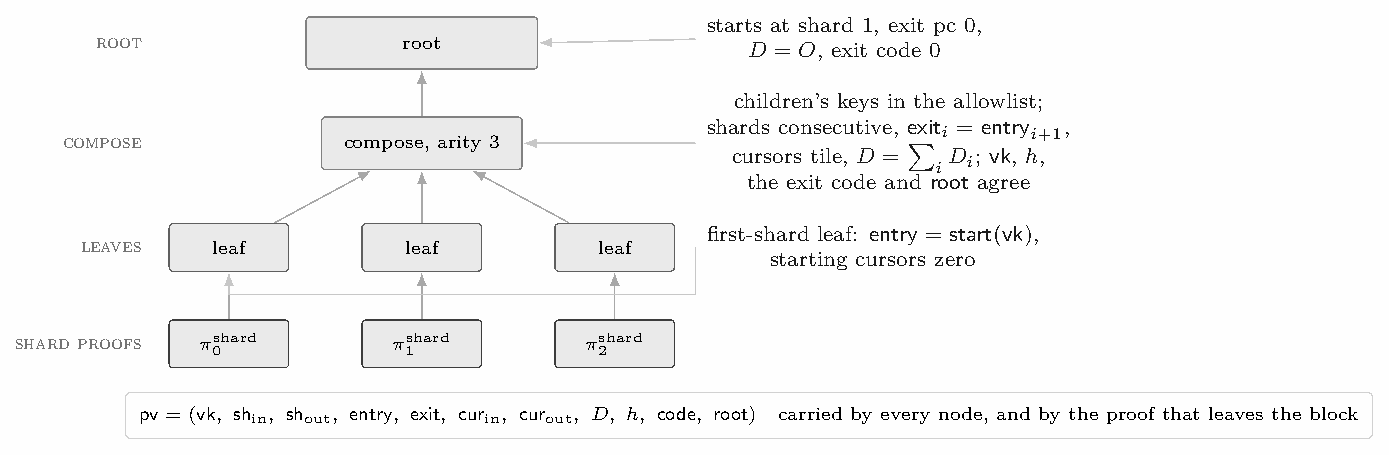
Leaves and the root. A leaf proves the same relation for its one or more fused children, except that each child is a core shard proof verified against the guest’s \mathsf{vk}; it is the leaf’s own key that the allowlist must contain, checked by its parent. A leaf sets \mathsf{sh}_{\mathrm{in}} and \mathsf{sh}_{\mathrm{out}} from the shard indices it verifies. The leaf of the first shard, index 1, also requires its entry state to be \mathsf{start}(\mathsf{vk}), the start state the guest key fixes, and its starting cursors to be zero. The root additionally requires \mathsf{sh}_{\mathrm{in}}=1, so that its leftmost leaf is the first-shard leaf. It also requires an exit program counter of zero, which the halt row sets (§5.10.4), D the identity and exit code zero, and it sets \mathsf{complete}, which closes the memory argument and the cross-shard digest over the execution and requires the exit code zero that the relation of Section 4.4 admits. Algorithm 2 states the checks.
Tree shape. The tree merges contiguous shard ranges as soon as they are complete rather than level by level, which shortens the tail after the last core shard from four serial composes to two, followed by the root (§3.3). A leaf is never the root, and neither is a compose of several children: once one node covers the execution, a compose of arity one over it closes the run, keeping leaf programs within the classes the enumeration below covers and giving the root one verifier program per child class, whatever the tree below it. The root alone is proved under the compress schedule (§10.4). Arity is capped at three by the recursion chips’ height budget; arity four was measured as neutral (41 nodes replaced by 27, −0.7% of wall time, unchanged tail).
Verifying-key binding. Each compose node checks its children’s recursion keys against a Merkle allowlist whose root it exports as a public value; why that binds the proof to the advertised machine, and what the external verifier checks of the root, are explained in §9.4.
Enumerating the leaf keys. A leaf program is determined by the geometry of the shard proof it verifies, which Section 6.6 quantises into buckets with a padding-column count fixed by the bucket. What remains is the shard’s chip set, one of the machine’s declared clusters, whether it is the execution’s first shard, and the two bucket indices. Enumerating those combinations yields, without running a guest, every leaf key a prover can produce for a shard in those clusters, at most 2\,|\mathcal C|\,|\mathcal B_{\mathrm{prep}}|\,|\mathcal B_{\mathrm{main}}| of them. A cluster is a chip-set combination declared by the shape configuration, curated from the target workloads rather than exhaustive over the chip powerset, so the allowlist covers an arbitrary guest only as far as the list does (§1.7). A shard outside the list produces a key the allowlist lacks and is refused: a loud failure of completeness, not of soundness. For the configuration this paper describes, the allowlist holds 6 362 leaf and compose keys. Sampling the leaf keys from a corpus of proved shards instead would leave every shard shape the corpus missed outside the allowlist. The enumeration is checked against such a corpus class by class and against the programs the classes generate. Algorithm 3 states it; every quantity it ranges over is fixed by the machine and the committed geometry.
Algorithm 2: The compose node of arity k, and what the root additionally requires. Line 2 is the binding of §9.4: without it the node would verify some proof rather than a proof of this machine.
Input: child proofs \pi_0,\ldots,\pi_{k-1} with public values \mathsf{pv}_0,\ldots,\mathsf{pv}_{k-1}, recursion keys \mathsf{vk}^{\mathrm{rec}}_0,\ldots,\mathsf{vk}^{\mathrm{rec}}_{k-1} and membership paths \mathsf{path}_0,\ldots,\mathsf{path}_{k-1}; a claimed allowlist root \mathsf{root}
Output: the node’s public values \mathsf{pv}, or \bot
Algorithm 3: Enumerating the admissible leaf and compose keys. The loop bounds come from the machine’s chip clusters and from the bucket rule of §6.6; no guest is executed.
Input: chip clusters \mathcal C; bucket sets \mathcal B_{\mathrm{prep}},\mathcal B_{\mathrm{main}}; padding rule \mathsf{pad}(\cdot)
Output: the allowlist root \mathsf{root}
The applications of §3.5 extend the tree past the root with nodes of arity one. Each verifies one child proof, checks the child’s key against the allowlist, and re-exports the child’s public values, so the statement is unchanged as the proof moves between configurations; the nodes differ only in the configuration they are proved under and in the verifier that reads their proof.
Shrink. A shrink node verifies the compressed proof under the compress schedule. One program has two variants, which differ only in how its proof is committed. The Poseidon2 variant is proved under the core configuration, KoalaBear traces and Poseidon2 commitments and transcript, and is the wrap’s input. The Blake3 variant commits the same traces, and runs its transcript, under Blake3, opened by jagged WHIR at a low rate, and is the binary stage’s input (§3.5).
Wrap. A wrap node verifies the Poseidon2 shrink. Its traces stay over KoalaBear, while its Merkle trees and transcript use Poseidon2 over the BN254 scalar field; the transcript absorbs KoalaBear elements several to one BN254 element and draws its KoalaBear challenges from BN254 outputs. A circuit over BN254 that verifies the wrap proof therefore hashes in its native field and emulates only the KoalaBear arithmetic.
The SNARK circuit. A Groth16 [Gro16] or PLONK [GWC19] circuit over BN254, written with gnark [Con24], verifies the wrap proof. Its public inputs are a hash of the guest’s key, the digest of the committed values and the allowlist root, read from the public values the wrap re-exports. The circuit checks no allowlist; it binds the wrap key itself, in one of two variants.
In both, an on-chain verifier checks the proof with a constant number of pairings.
This section collects the security argument. It states the relation the block proof is an argument for (§9.1), the concrete soundness of each proof (§9.2), how those levels compose into a statement about the non-interactive block proof (§9.3), how the verifying keys tie that proof to the advertised machine (§9.4), the one assumption that is not about hashing (§9.5), what makes the satisfying trace unique (§9.6), why it is the MIPS32 execution, with the determinism of every extracted chip machine-checked in Lean 4 (§9.7), and what changes against quantum adversaries (§9.8). Every hypothesis the end-to-end statement carries is named in this section, and the ones that remain open are listed together in §9.1.
The shard argument proves one shard; the statement of Section 4.4 is about an execution. Between the two sits the arithmetised relation the recursion tree is knowledge sound for, displayed, as Ceno displays its own [LZZ+24], with each part assigned to the component that discharges it:
\mathcal{R}_{\mathrm{arith}}=\left\{(\mathsf{vk},h)\ :\ \begin{aligned}&\exists\,(\mathsf T_i,\mathsf{pv}_i)_{i<N}\ \forall i:\ \mathsf T_i\text{ is a valid shard for }\mathsf{pv}_i\text{ and }\mathsf{vk},\ h_i=h && \text{(shard argument)}\\ &\wedge\ \forall i<N-1:\ \mathsf{sh}_{i+1}=\mathsf{sh}_i+1,\ \mathsf{exit}_i=\mathsf{entry}_{i+1},\ \mathsf{cur}_{\mathrm{out},i}=\mathsf{cur}_{\mathrm{in},i+1} && \text{(compose nodes)}\\ &\wedge\ \mathsf{entry}_0=\mathsf{start}(\mathsf{vk}),\ \mathsf{cur}_{\mathrm{in},0}=0 && \text{(first-shard leaf)}\\ &\wedge\ \mathsf{sh}_0=1,\ \mathsf{pc}(\mathsf{exit}_{N-1})=0,\ \textstyle\sum_i D_i=\mathcal O,\ \forall i:\ \mathsf{code}_i=0 && \text{(root)}\end{aligned}\right\}
Validity is Definition 2.6; \mathsf{sh}_i, h_i and \mathsf{code}_i are fields of \mathsf{pv}_i; the halt row sets the exit program counter to zero; \mathsf{start}(\mathsf{vk}) is the start state the key fixes; the entry and exit states are program-counter pairs; \mathcal O is the identity of the digest’s curve group; the cursors tile the address space; D_i is the shard’s cross-shard digest net of the offset D_{\mathrm{off}} of §5.5. Theorem 9.2 (§9.3) is knowledge soundness for \mathcal R_{\mathrm{arith}}, and Theorem 9.6 (§9.6) with the conformance evidence of §9.7 is what connects \mathcal R_{\mathrm{arith}} to \mathcal R, through Lemma 9.5, which joins the shards’ memory into one execution.
What is proved, in one place. Theorem 9.2 bounds a cheating prover for the whole tree by the number of random-oracle queries times the sum of the per-node errors, plus the hash and digest terms, under a per-node round-by-round premise, a hypothesis about composed extractors and the hypothesis that the leaf and compose programs enforce the compose relation. Theorem 9.6 shows that two valid shards for the same program image and public values, which also agree on the initial values of the words they touch and on the values the chips leave to the prover by design, agree up to permutation on the rows reachable from the entry state, given chip determinism (§9.7) and real-row exhaustiveness; identifying that trace with an execution needs the conformance evidence of the same section. Neither statement depends on a particular chip set, field or proximity test. §9.3 places Theorem 9.2 as the last of three layers, after the functional IOP and the interactive commit-and-open argument, and states which hypothesis each layer carries.
Open hypotheses. The end-to-end statement holds under five hypotheses that this paper does not discharge:
Conformance evidence (§9.7), not a proof, identifies the arithmetised machine with the MIPS32 instruction set.
Table 7: What the determinism statements exposed. Each row is a chip whose statement, as first extracted, did not hold; the last column is how the constraints or the statement were changed. The three new constraint sets change the verifying key.
| Chip | What the statement exposed | Consequence | Resolution |
|---|---|---|---|
*DoubleAssign (secp256k1, secp256r1, BN254, BLS12-381) |
The slope gadget proves s\cdot2y=3x^2+a and nothing about 2y. For an input with y\equiv0, such as (0,0) on a curve with a=0, every slope satisfies the chip, and the row writes (s^2,-s^3). | Soundness gap: the written point is the prover’s choice. An AIR-level test forges it for three slopes. | An inverse check proves \mathsf{is\_real}/2y exists, and the executor refuses y\equiv0. |
Global (flags) |
\mathsf{is\_send} and \mathsf{is\_receive} choose the sign of the lifted point’s y and were neither boolean nor tied to \mathsf{is\_real}: with both zero, (x,y) and (x,-y) both satisfy the row and give different digests. | Soundness rests on the senders: every current sender sets exactly one flag, so a (0,0) row cannot balance the bus today. SP1 v6 constrains the flags the same way. | Both flags boolean and \mathsf{is\_send}+\mathsf{is\_receive}=\mathsf{is\_real}. |
KeccakSpongeControl |
Of a multi-block sponge, only the first block’s input and output addresses were bound to the syscall; later blocks’ addresses were free, and nothing tied the number of blocks to the input length. | Soundness gap: a prover can absorb later blocks from any address, stop early or late, and write the digest anywhere. | Each block carries the input address, output address and length on the block bus; the first block is block 0 and binds the length read from memory, its top byte range-checked; the final block has (b+1)\cdot36=\mathit{len} (36 words, the chip’s 1152-bit rate). |
Global |
The lift_x offset is a byte the prover picks among those that lift the message to a curve point. |
None: the encoding stays injective because the top message field is below 2^{16}; SP1 is the same. | The offset is an input of the statement. |
SyscallInstrs |
The length of a hint read is chosen by the host. | None: hints are untrusted input by definition. | The hint length is an input of the statement. |
MemoryGlobalInit |
The address and value of an initial-memory row are the prover’s choice. | None: the global memory argument fixes them against the image and the first access. | Address and value are inputs of the statement. |
The verifying key depends on the chip set (§8) and the committed geometry is quantised from declared heights (§6.6), so the argument must reject a shard whose declared shape is false. A harness proves real shard proofs for an arithmetic and a hash-heavy guest and tampers with them in eighteen ways: over- and under-claimed heights, false chip activity, and tampered column and row counts, each injected into the degree mask, the Fiat–Shamir prologue, or both. Every case is rejected: height and activity lies in the degree mask by the LogUp-GKR last-layer reconstruction, lies confined to the transcript by the grinding witness (the prologue observes the declared heights), a tampered column count by the jagged verifier, and a tampered row count by the preprocessed round, which reads it from the verifying key.
Every component of the shard and recursion arguments except the elliptic-curve multiset hash is hash-based: the Merkle commitments under \mathsf H, the WHIR (or BaseFold) proximity test, the sumchecks and LogUp-GKR. The Fiat–Shamir compilation of such interactive oracle proofs remains sound against quantum adversaries in the quantum random-oracle model [CMS19], with weaker concrete bounds: a quantum collision search on the 248-bit digest of the measured instantiation costs about 2^{83} rather than 2^{124} evaluations [BHT98], so the levels of §9.2 are classical. The digest is the exception. Shor’s algorithm computes discrete logarithms in E(\mathbb F_{p^7}) [Sho97], which reduces Assumption 9.4 to finding a short integer relation among known scalars, and at the interaction counts of a block such a relation should be assumed easy to find. Against a quantum adversary the options of §5.5 therefore differ: the global challenge and Merkle roots rest on hashes, and a lattice multiset hash on a problem not known to be easy for quantum adversaries, while the elliptic-curve multiset hash does not survive. Table 3 gives their costs; this paper claims post-quantum security for no configuration.
Of the two hash-based options, Merkle roots perform best: on one GPU, where the card is the bottleneck, their smaller committed area makes them faster; on four GPUs their proving work is smaller but arrives in execution order, and the cards idle while the last leaves and compositions of a block drain, a tail the elliptic-curve multiset hash fills with its independent precompile and memory shards.
Remark 9.7 (Real-time quantum adversaries). Proving a block in time close to linear in its trace does not by itself protect the elliptic-curve digest. The lift applies no salt: a point is a fixed function of its message, so a quantum adversary can compute a vanishing combination once, offline, and reuse it in a false proof for any later block, and the speed of honest proving does not bound that attack. A time-bounded claim holds under two further conditions, neither of which the configuration of this paper meets. (i) Salting: the lift mixes a per-block value \sigma that is unknown before the block is fixed, such as the block hash or a challenge drawn after the shards’ trace commitments, constrained in the chip and checked by the verifier, so that a relation among one block’s points is useless for another. (ii) Timeliness: a proof for block b has value only if it is delivered within a window \omega after b appears, as in real-time proving where a late proof is not consumed. Under (i) and (ii) an adversary must find its relation for block b’s salted points within \omega, while the honest proof, and its verification, completes in about the honest proving time; if solving the discrete logarithms such a relation needs takes longer than \omega, the forgery arrives after the proof has lost its value, and fast proving lets \omega shrink toward the honest proving time, 10 to 31 s per block on four GPUs for the twelve blocks of Table 3. This is a threat-model argument, not a theorem. It needs (i), which changes the digest and the verifying key; a lower bound on quantum discrete-logarithm time, which we do not have; and a deployment rule that enforces \omega. It gives no protection after \omega, and none for proofs that keep their value later, such as archived or bridged proofs.
We evaluate three quantities: instruction efficiency, the committed area and bus interactions an executed instruction costs, which is a property of the arithmetisation (§10.2); proving efficiency, the rate at which an implementation turns that area into a proof on named hardware (§10.3); and proof size, the bytes of the compressed proof a verifier reads, with the parameters that control it (§10.4). One primary workload, one GPU model and one host are used, with interleaved repetitions, so that differences between configurations are attributable. No cross-system comparison is attempted: other systems’ figures are self-reported on different guests and mostly on clusters, and nothing here is a same-hardware baseline. The evaluation is controlled: fixed blocks are measured so that configurations are compared on identical input.
Workload. Ethereum mainnet block 25 907 955, executed by a MIPS32 build of the reth execution client with an arena-represented witness trie; the guest hashes trie nodes, recomputes a Merkle root over state it does not hold and verifies signatures. A word-wise memcmp, a zero-copy Keccak wrapper and the arena trie reduce it from 379 to 288 million cycles. The single-GPU timing of Memory traffic and shard size (§10.3) uses that cached record; the multi-GPU measurements of §10.3 add blocks of 420, 530 and 912 M cycles, and the instruction-efficiency census of §10.2 uses block 25 955 640 (495.6 M cycles) in the analysed configuration.
Hardware. One NVIDIA RTX 5090 (32 GB) in a virtual machine with eight such GPUs, 124 vCPUs of AMD EPYC 9355 and 925 GB of memory; the multi-GPU runs use four (driver 570.153.02, CUDA 12.8, Ubuntu 22.04). The GPU backend is a separate CUDA implementation of the same protocol and is not open source.
Configurations. Sections 5–9 describe the analysed configuration. The timings below, and the proof-size comparison of §10.3, were taken on an earlier measured configuration, which differs in four respects: the Poseidon2 permutation used 13 partial rounds rather than the corrected 20; the lookup challenge was not ground; the syscall bus carried the sum of two 16-bit half-words rather than the half-words themselves (§5.1); and the set of three soundness fixes of Table 7 was not applied, each of which adds constraints. The comparisons below are therefore internal to the measured configuration, and the soundness figures of §9.2 are for the analysed one. Unless a caption says otherwise, every timing below is of the measured configuration and every area of the analysed one.
Metrics and protocol. Trace area is the sum over chips of rows × columns from the emulator’s shard-close census; Table 9 takes its kernel shares from the measured configuration. Wall-clock time runs from reading the cached input to writing the compressed proof and includes 2–3 s of host verification of the proof; proving throughput is guest cycles divided by it, and is not a clock frequency. Proof size is the serialised compressed proof. A ten-shard nsys sample attributes kernel time. Table 10 reports three consecutive warm proofs per configuration, warm meaning after a first proof has loaded the keys and compiled the programs. Medians are reported, and the spread was within ±0.8 s for Table 10. The measured GPU was otherwise idle, but an unrelated proving process ran on another GPU of the host.
We first estimate what one executed instruction costs, from the chip widths and interaction counts of §§5.9 and 5.10, in committed cells and bus interactions (§1.3). Table 8 counts an instruction’s own row only; the memory-argument rows for each shard’s first and last access to a word, and the tables’ multiplicity columns, are paid per shard and are measured below.
Table 8: Committed cells and bus interactions per executed instruction, for the most frequent chips. The frame includes the program-counter pair; interactions count the program fetch, the state bus, the memory bus and table lookups.
| Chip | cells: frame | cells: own | cells: row | interactions: frame | interactions: own | interactions: row |
|---|---|---|---|---|---|---|
AddSubImm |
29 | 4 | 33 | 16 | 0 | 16 |
AddSub |
32 | 4 | 36 | 20 | 0 | 20 |
Bitwise |
32 | 5 | 37 | 20 | 4 | 24 |
Lt |
32 | 18 | 50 | 20 | 3 | 23 |
ShiftLeftImm |
26 | 19 | 45 | 16 | 4 | 20 |
ShiftRight |
32 | 57 | 89 | 20 | 25 | 45 |
Branch |
29 | 27 | 56 | 16 | ≤ 9 | ≤ 25 |
LoadWord |
29 | 19 | 48 | 16 | 9 | 25 |
StoreWord |
29 | 23 | 52 | 16 | 9 | 25 |
LoadNarrow |
29 | 30 | 59 | 16 | 10 | 26 |
Mul |
32 | 42 | 74 | 20 | 22 | 42 |
DivRem |
32 | 131 | 163 | 20 | 44 | 64 |
Per instruction. The frame is most of every common row: an addition or bitwise operation pays 29–32 cells and 16–20 interactions of frame for at most five cells and four interactions of its own, so the per-instruction floor is set by the register memory check. Expensive instructions are expensive in columns, not rows: a division is one row of 163 cells where Jolt’s sequence takes eight steps [AST24]. Per-opcode chips are what keep the common rows narrow: one table carrying every opcode’s columns would pay the widest row on every instruction, over 400 cells (MiscInstrs alone has 432 columns) where the common instructions pay 33 to 37; SP1 makes the same choice [Suc24].
Per block. Block 25 955 640, 495.6 million cycles, commits 29.2 G cells and raises 12.8 G (row, interaction) pairs, 58.9 cells and 25.8 pairs per executed instruction (Table 9, Figure 8a). This is larger than the single-row costs of Table 8 mainly because of the per-shard memory-argument rows: the Global chip holds 15% of the area, 8.8 cells per instruction, because every word a shard touches costs two rows of it, which is the cost of sharding. The figure depends on the workload, not only on the instruction set. A precompile call is one guest cycle and many rows of an accelerator chip, and since a shard closes when its committed area reaches 4.6\cdot10^8 cells, the precompile share sets both the cells per cycle and the shard count: two mainnet blocks of 949 and 943 million cycles proved in production as 702 and 213 shards. These are cells of a 31-bit field and do not convert into Jolt’s bit-weighted count.
What reducing area buys. The census says where to cut: area for the commitment and constraint argument, pairs for the bus argument. Two changes follow from it, both mechanisms rather than tuning: replacing a boolean sign decomposition in the cross-shard digest chip with three byte lookups, and dropping byte checks on memory-instruction accesses that another chip already enforces. Both change the constraint system, and with it the chip keys and the recursion-key allowlist; neither changes the statement proved.
Where the time goes. Kernels account for about 340 ms of the 500 ms of GPU time per shard, launch gaps and host synchronisation the rest (Table 9, Figure 8b). The lookup argument is the largest consumer, and its cost scales with (row, interaction) pairs rather than with columns: memory-instruction chips carry 25–26 interactions per row and 47% of all pairs, while the Global chip holds 15% of the area but 3.7% of the pairs. The cost model is therefore area for the commitment and zerocheck and pairs for the lookup, one pair weighted as about two cells.
Table 9: LogUp-GKR consumes 42% of kernel time, and LoadWord, Global and StoreWord hold about 15% of the trace area each. Kernel shares are from a ten-shard nsys sample; area is rows × columns from the executor’s census of block 25 955 640 (29.2 G cells).
| Kernel group | share | Chip | area share |
|---|---|---|---|
| LogUp-GKR layers (fold-and-sum, transitions, first layer) | 42% | LoadWord (92.6 M rows × 48) |
15.2% |
| Zerocheck, compiled constraint kernels | 16.5% | Global (67.2 M × 65) |
15.0% |
| Zerocheck, interpreted (wide precompile chips) | 7.1% | StoreWord (81.8 M × 52) |
14.6% |
| Zerocheck fold | 2.3% | MemoryUnaligned (42.7 M × 59) |
8.6% |
| WHIR commit and open (Merkle absorb, DFT) | 19% | Branch (36.1 M × 56) |
6.9% |
| Jagged reduction | 8% | AddSubImm (59.4 M × 33) |
6.7% |
| Other | 5% | ShiftLeftImm (34.8 M × 45) |
5.4% |
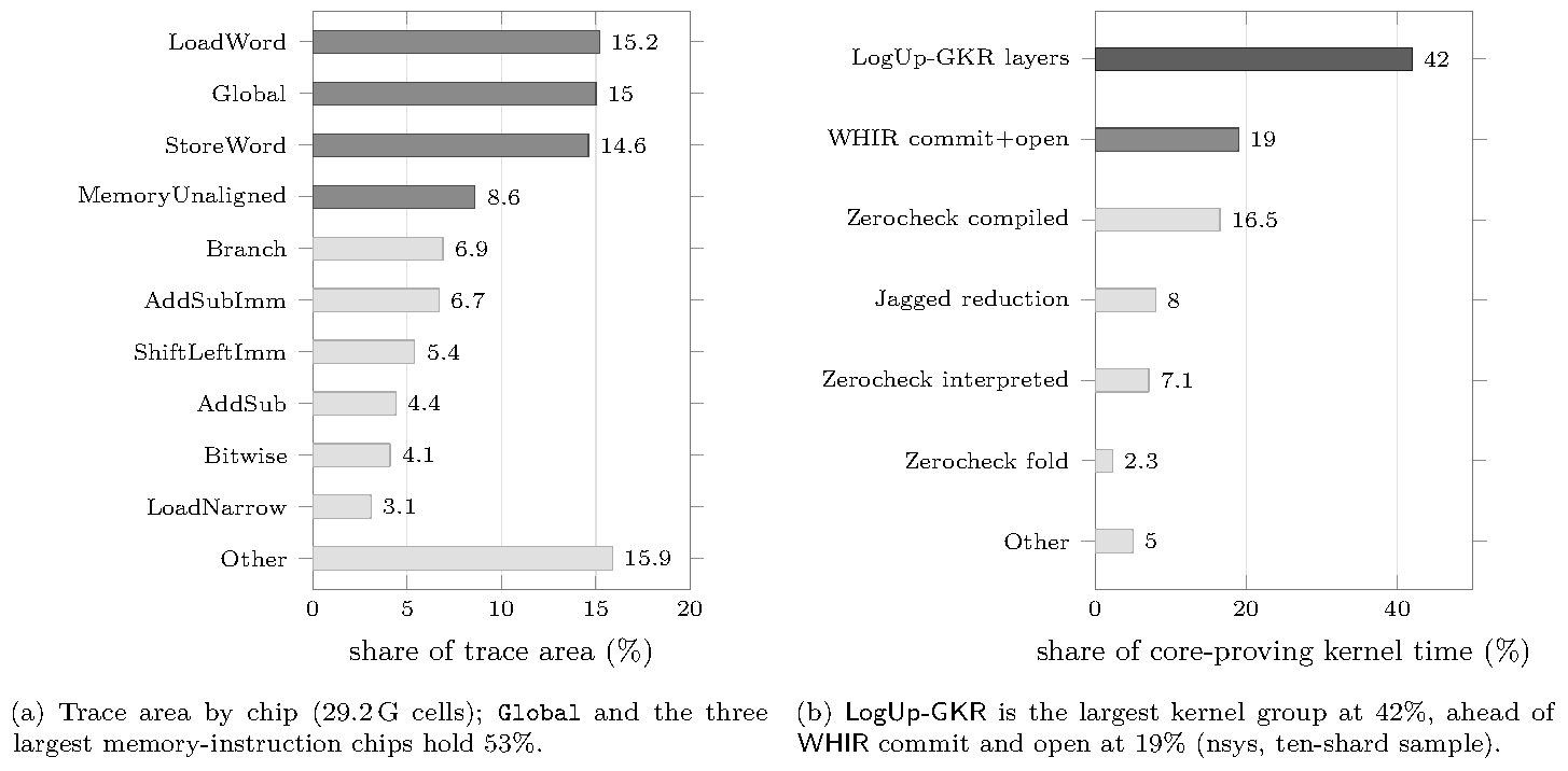
Global and three memory-instruction chips hold 53% of the trace area of block 25 955 640, and LogUp-GKR takes 42% of kernel time. (a) Trace area by chip (29.2 G cells); Global and the three largest memory-instruction chips hold 53%. (b) LogUp-GKR is the largest kernel group at 42%, ahead of WHIR commit and open at 19% (nsys, ten-shard sample).Memory traffic and shard size. A byte-level profile of the LogUp-GKR circuit showed that its first layer paired fractions across the most-significant index bit, so short chips were carried through every layer of the tallest and the traffic summed over layers was 5.2× that of the first. The prover therefore pairs on the least-significant bit, so each chip folds out after \log_2 of its own height, and the memory this frees admits shards of twice the size. The two changes are enabled together: the old-pairing, doubled-shard configuration does not fit in memory, so their effects are not separated. With both, the cached 288 M-cycle block 25 907 955 proves in 48.7 s on one GPU (5.9 MHz), against 67.8 s for the revision without either at the largest shard size it could run (−28%), with the compressed proof unchanged in size.
Scaling across devices. Table 10 and Figure 9 report proving throughput on one to four GPUs for blocks of 420, 530 and 912 M cycles. Throughput varies by at most 20% across blocks and scales by 1.9× to two GPUs and 3.1–3.3× to four, reaching 20–24 MHz. The gap to linear scaling is the serial recursion tail and the start-up interval before the emulator has produced a shard for every GPU.
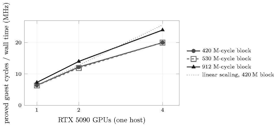
Table 10: Four GPUs reach 3.1–3.3× one-GPU throughput (20–24 MHz) on all three blocks. Median warm wall-clock time of three consecutive proofs.
| Block (guest cycles) | wall-clock (s): 1 GPU | 2 | 4 | throughput (MHz): 1 GPU | 2 | 4 |
|---|---|---|---|---|---|---|
| 420 M | 65.9 | 34.3 | 21.0 | 6.4 | 12.2 | 20.0 |
| 530 M | 84.3 | 44.7 | 26.5 | 6.3 | 11.9 | 20.0 |
| 912 M | 124.3 | 65.0 | 38.0 | 7.3 | 14.0 | 24.0 |
The host. On one core of an AMD EPYC 9355, the just-in-time compiler executes block 25 955 640 (496 M cycles) at 198 MHz once compiled (166 MHz including its single compilation pass), and the interpreter at 40.6 MHz without the event record and 14.6 MHz with it; the coordinator’s whole producer job takes 6.1 s for a 420 M-cycle block, some 69 MHz. On one GPU, emulation does not bind. It binds when one host feeds several GPUs, because each shard is re-emulated by the worker that proves it, at about one second of host time per shard against half a second of GPU time, so the event record carries only what a column witnesses and the coordinator never holds the whole execution (§3.1).
Where the GPU work sits. Three kinds of engineering act on different costs. Fused kernels cut memory traffic: the jagged fold and the round polynomial it feeds are one kernel, as are the layer transition and the round over the mixed round-0 slab. A cross-stage pipeline cuts idleness: leaves and compose nodes are proved while core shards are still being proved (§3.3). Occupancy tuning caps the register budget for the measured card. Field arithmetic rests on the inline-PTX Montgomery primitives of sppark [Sup25], which we use and did not write.
What the soundness target costs the prover. The level of §9.2 is paid for in queries and in proof-of-work. We measured the grinds separately, on four GPUs, at a build that grinds the lookup challenge, with the arms interleaved on one cached block. The 22/22/14-bit query, LogUp-GKR and batching grinds took 33.4 s against 33.9 s for 16/16/8, a difference within run-to-run spread, while buying the same bits with queries (133, 95 and 91 queries in the three WHIR rounds at a 16-bit grind) cost 8.6%. That holds only because the search runs on the device: with the grinds on the host the same schedule took 166 s, 123 s of it the LogUp-GKR grind.
The shard proofs of a block total on the order of 10^8 bytes before recursion; the published object is the compressed proof at the root of the tree, whose size does not grow with the execution. It is dominated by the openings of the first WHIR oracle, about four fifths of it in the instrumented proofs, because each query authenticates one coset row of every stripe; the later WHIR rounds, the LogUp-GKR layer proofs and the other sumchecks share the rest. To first order the size is
t_0\cdot\big(\text{stripes}\cdot2^{k_0}+\text{roots}\cdot\log_2(\text{leaves})\cdot|\text{digest}|\big)+\sum_{i\ge1}t_i\cdot(\text{folded leaf}+\text{path}),
with t_i the queries of round i and k_0 the first folding factor. Every lever on it is a parameter of the schedule (§7), fixed per stage, and each trades against something else at a fixed soundness level:
The parameters that make the proof small need to apply only to the published proof: the core shards and every recursion node below the root keep the schedule tuned for prover time, since each of those proofs is consumed by its parent and never leaves the prover, and the root alone proves under the compress schedule of Table 5. The root is a compose of arity one over the node that covers the execution (§8), so its verifier program, and with it the committed area that sets the number of stripes, is the same small one for every tree, and it fits the smallest area class, 16 stripes per round. The two schedules are two instances of one ring type, so the field, the hash and the transcript are shared and only the schedule differs; a verifier takes the schedule from the stage it expects, never from the proof, and every parameter of the compress schedule is a setting, so a different security requirement is a different schedule under the same prover.
Taken together, the Johnson-bound schedule at a first rate of 2^{-3} with k_0=2 roughly halves the first-oracle openings against the unique-decoding schedule at rate 2^{-2} with k_0=3, at the same union soundness (Table 6), for 27 bits of grinding on the folding and batching challenges, paid once per proof at the root, which is the prover-time cost of the smaller proof. Measured on the analysed configuration with a fibonacci guest, whose root verifier program is that of any block, the compressed proof is 280 653 bytes (274 KiB) under the compress schedule, against 846 401 bytes when the root proves under the core schedule; since the root program is the same for every tree, the size does not depend on the guest. The native verifier checks it in 73 ms (median of five runs, 63–89 ms) on the host of §10.1. This run omits the in-circuit allowlist check of the root’s children, since the guest’s leaf key lies outside the enumerated clusters (§8).
Internal. Comparisons are interleaved and repeated, and the spread is small relative to the effects reported; the host processor was shared with an unrelated process. Construct. Every timing and proof-size measurement predates the Poseidon2 correction, which adds seven partial rounds to commitments, transcripts and recursion and changes absolute performance by an unmeasured amount; the ablations are evidence about mechanisms to the extent the correction leaves relative costs unchanged. Wall-clock time includes host verification, and trace area is a model where the kernel profile is the measurement. The pipelining of §3.3 is not ablated: no run defers recursion until every shard is proved, so its effect on wall-clock time is not separated from the rest. External. The primary workload is one Ethereum block, and other guests have different instruction mixes. The raw per-run timings are not retained, and the retained area census is for the analysed configuration rather than the measured one.
We have presented Ziren, a succinct argument for MIPS32 execution. Its architecture is one proving stack whose compressed proof a native verifier checks, with applications built on it that verify that proof inside other proof systems: a pairing-based SNARK for an on-chain verifier, and, through a change of hash and then of field, a garbled verifier whose cost is counted in AND gates and input bits (Section 3). One row of one chip per executed instruction, carried by an instruction frame, replaces the CPU table; one lookup argument and one zerocheck per shard discharge every bus and constraint; a jagged reduction opened by WHIR commits columns of any height at the cost of their real area; and a recursion tree with an enumerated key allowlist composes the shards into one proof. Conformance suites and an executable Lean 4 model test the emulator. Determinism is extracted from the constraint description the prover evaluates and proved by replaying a propagation analysis as step lemmas over gadget theorems proved once; all 104 extracted theorems are closed in Lean 4, the statements exposed three soundness gaps that the constraints now close, and the same pipeline extends to the remaining control chips and to the recursion machine.
Beyond determinism, two techniques surround the machine. Proving is pipelined: shards are proved as the emulator produces them, recursion nodes are proved while core shards are still in flight, and trace generation and the proof-of-work searches run on the device, so what remains serial is the start-up interval and the recursion tail (§3.3). And cross-shard memory has four options: an elliptic-curve multiset hash, the one component that is not hash-based; a lattice multiset hash, which would cost no less than 19.6× the committed area; a global challenge, 29 to 42% slower; and Merkle roots over touched memory, faster on one GPU and 3.4% slower on four (§§5.5 and 9.8).
The performance study identifies trace area, lookup interactions, layer order and shard size as distinct cost levers. The two largest costs it identifies are the lookup argument, 42% of kernel time, and the cross-shard digest, 15% of the block’s area, which a digest of per-shard deltas or a larger shard would reduce. The open proof obligations are the five hypotheses of §9.1; future work should measure the corrected Poseidon2 schedule against one configuration, soundness report, key set and proof.
The Plonky3 [Pol24] toolkit supplies the field, the Poseidon2 permutation [GKS23], the constraint interfaces and the transforms this implementation is written against. We thank the developers of SP1 [Suc24, Suc25a] and OpenVM [Ope26b] for publishing their systems openly; the components of theirs that this paper uses are cited where they are used.
This appendix itemises the columns and interactions of the instruction frame (Table 11) and the width of every chip (Table 12).
Table 11: Columns of the R-type instruction frame. The I-type frame replaces the \mathsf{op\_c} index and access (7 columns) by a word immediate (4), 27 columns in all; the shift-amount frame replaces them by a scalar immediate (1) and drops the access, 24 columns. The program-counter pair is owned by the chip and passed to the frame.
| Element | Purpose | Columns |
|---|---|---|
shard |
shard index, the high part of every timestamp; 16-bit range check | 1 |
clk limbs |
the instruction’s clock as a 16-bit and a 10-bit limb, both range-checked | 2 |
opcode, op_a, op_b, op_c |
the decoded instruction, sent on the program bus with pc |
4 |
op_a_0 |
set when the destination is register 0, which pins the written word to zero | 1 |
op_a access |
previous word, written word, previous timestamp and one limb of the timestamp difference | 10 |
op_b access |
word read, previous timestamp, one difference limb | 6 |
op_c access |
word read, previous timestamp, one difference limb | 6 |
| Frame | 30 | |
pc, next_pc |
the counter pair received on the state bus; owned by the chip | 2 |
The R-type frame raises 20 interactions per row: one program fetch; a receive of (\mathsf{shard},\mathsf{clk},\mathsf{pc},\mathsf{next\_pc}) and a send of (\mathsf{shard},\mathsf{clk}+5+\delta,\mathsf{next\_pc},\mathsf{next\_next\_pc}) on the state bus, where \delta is zero except for a system call; a send of the previous and a receive of the new tuple on the memory bus for each of its three accesses; and eleven table lookups, one 16-bit check of the shard, two for the clock limbs, two per access for the timestamp difference, and two for the four bytes of the written word, which the byte table checks in pairs. The I-type and shift-amount frames have one access fewer, and raise 16.
Table 12 lists all 62 chips with their widths in the analysed configuration. Global differs most from the measured configuration: it has 65 columns here, against 100 in the measured baseline and 58 after the change of §10.2, because the analysed configuration keeps seven chord-witness columns that change removed.

