Abstract
This document introduces zkMIPS, an advanced Zero-Knowledge Protocol (ZKP) system designed for MIPS architecture. zkMIPS aims to provide a verifiable computing solution to trust the computation results generated by untrusted computers. The adoption of the MIPS architecture aligns perfectly with the vision of incorporating zkMIPS into diverse domains such as blockchains and IoT. In the blockchain realm, zkMIPS is seamlessly integrated with blockchain Layer 2 technologies, offering a ZKP layer 2 rollup solution. By harnessing the power of ZKP and leveraging the robustness of the MIPS architecture, zkMIPS aims to fulfill its objectives effectively. In non-blockchain systems including the Internet of Things (IoT), Virtual Reality (VR), decentralized cloud computing, and zero-knowledge machine learning (zkML), zkMIPS enables a secure communication channel by trusting devices’ computation results. This document serves as a comprehensive introduction, shedding light on the zkMIPS system as well as the possible integration with Layer 2 blockchain projects to offer a hybrid rollup solution.
In recent years, the advancement of verifiable computing techniques, particularly in zero knowledge proofs (ZKPs), has enabled developers to ensure the trustworthiness of com putation results from untrusted parties. Among these achievements, zkMIPS introduces a mechanism to demonstrate the integrity of any MIPS computation. Although initially focused on layer 2 zero-knowledge (ZK) rollup solutions, zkMIPS holds broad applicability, including Internet-of-Things (IoT), wearables, and more. zkMIPS facilitates quick and easy proof of the validity for the computation results performed by untrusted parties, offering a robust solution to ensure computational trust in a wide range of practical applications.
In a ZKP system, one of the parties, called the Prover, wants to convince the other party, the Verifier, that it possesses specific information [13, 14]. This can involve proving knowledge of a password, a specific solution to a problem, or the ability to execute a particular computation. Although existing methods in the area of ZKP are very promising, applying these techniques to develop a high-performance system requires further innova tion and careful consideration. zkMIPS aims to create a cryptographic proof that validates the execution of computations, with several concerns such as proof size, prover time, and verifier time. The generated proof should be succinct to meet application requirements and minimize storage and transmission overhead. Balancing these factors requires on going innovation to ensure that zkMIPS can be applied effectively and should be easily integrated with existing applications with minimum effort.
zkMIPS is designed for the stable and well-established MIPS architecture to apply ZKP techniques resulting in offering numerous advantages. The adoption of MIPS architecture brings benefits, such as small instruction set and the simplified design of efficient ZKP circuits. Additionally, due to the stability of the MIPS architecture, integrating zkMIPS does not require significant alterations to its core design, making it compatible with systems that compile computations to MIPS. In the realm of blockchain, the player in Layer 2 solutions can accelerate the development of a ZKP rollup solution and enhancing scalability and privacy features by applying zkMIPS technology. Furthermore, zkMIPS is a natural choice for IoT applications, as the popularity of MIPS in IoT devices allows for the seamless incorporation of verifiable computing capabilities. In general, zkMIPS takes advantage of the strengths of the MIPS architecture, enabling the widespread implementation of ZKP techniques in domains ranging from blockchain solutions like Optimism to IoT, Virtual Reality (VR), wearable devices, and more applications.
This document serves as an introduction to zkMIPS technology, covering various aspects of its implementation. Section 2 provides a comprehensive review of the applied MIPS architecture within zkMIPS. Section 3 delves into the software system architecture necessary for seamless integration, while also highlighting the integration of Optimism technology for Layer 2 (L2) rollup purposes. The document proceeds to explore ZK protocols in Section 4, explaining how they provide succinct proof through the conversion of computations into high-degree polynomials over a finite field, enabling efficient verifica tion by the Verifier. This section further elaborates on the ZKP approach employed by zkMIPS. Finally, in Section 5, the document examines various zkMIPS applications, such as zkRollup, decentralized cloud computing, and their suitability for IoT devices. Section 6 concludes the document.
The Microprocessor without Interlocked Pipelined Stages (MIPS) is a well-known and widely adopted class of Reduced Instruction Set Computer (RISC) architectures that were developed by MIPS Computer Systems. Over the years, MIPS has gained significant prominence and found applications in various domains, including embedded systems and video game consoles.
While MIPS has a strong presence in the industry, other RISC-based architectures such as RISC-V have emerged more recently and are rapidly gaining popularity. One of the advantages of MIPS is its fixed set of instructions, which simplifies the design of stable zero-knowledge products for the market. In contrast, RISC-V offers a modular instruction set that allows the incorporation of new custom instructions. This flexibility can be advantageous in certain scenarios, but it also means that RISC-based zero-knowledge products may require more modifications in the future to adapt to the evolving instruction set.
In the realm of blockchain Layer 2 solutions, applying MIPS architecture results in less complicated circuits in ZK proof generation system. This makes MIPS an ideal fit for practical blockchain L2 solutions built upon it.
It is important to note that there are multiple versions of MIPS, and zkMIPS specifically utilizes MIPS32 [21], which refers to the 32-bit implementations of the MIPS R3000 architecture [17].
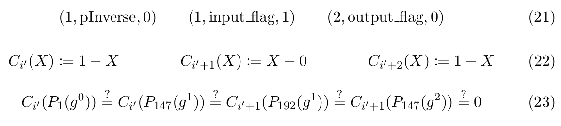
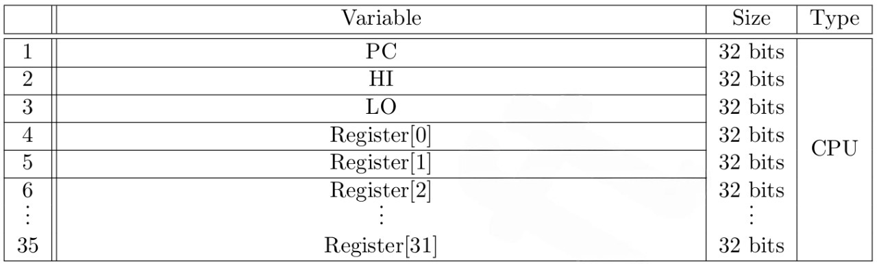
Any computation starts with a well-defined initial state and is then modified through a specific sequence of instructions. In the case of the MIPS processor, the associated state comprises various elements depicted in Figure 1.
By maintaining and modifying this state through a given sequence of instructions, MIPS processors perform computations and execute programs. The emulator applied in zkMIPS emulates a MIPS processor and operates on states to simulate the execution of MIPS instructions and computations. The MIPS architecture is depicted in Fig. 1. Also, the CPU registers are as follows.
In zkMIPS we implement MIPS-1 instruction set architecture (R3000), which consists of 69 instructions. We do not implement floating point instructions or coprocessor extensions. For a comprehensive list of these instructions, please refer to Appendix A.
In this section, we first review the main software components of the zkMIPS system. Then, we provide an example to demonstrate how to integrate zkMIPS with an L2 blockchain solution.
The software system contains four main components as follows.
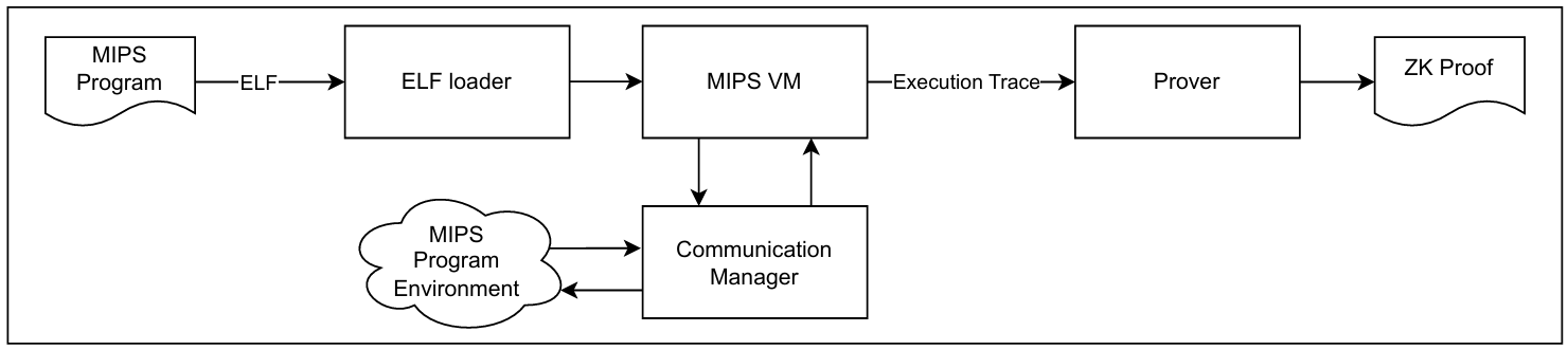
Any program written in C, Go, Rust, etc., can be compiled using a generally available MIPS compiler into MIPS R3000 BE ELF executable. The resulting ELF file is loaded into MIPS VM with the ELF loader. The VM executes the input executable. Communication Manager implements syscalls handlers, which can be used by MIPS program during execution. Finally, the MIPS VM generates an execution trace for the Prover. The Prover then creates a ZK Proof. The details of this last step will be explained in the next section.
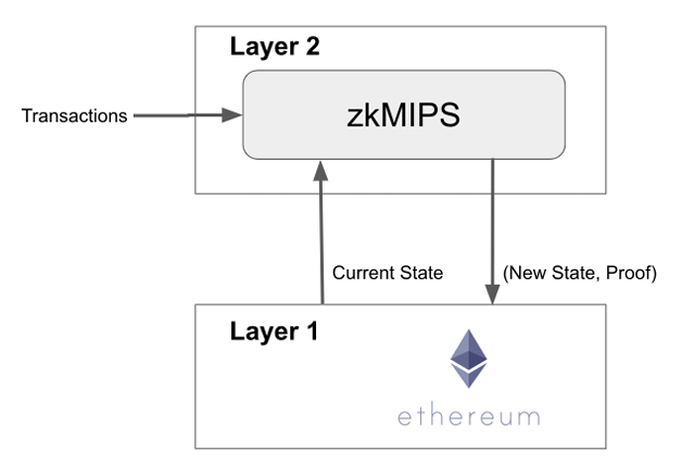
zkMIPS offers seamless integration with existing Layer 2 (L2) solutions, including the Optimism architecture [10]. One of the standout features of zkMIPS is its ability to generate succinct proofs, enabling support for ZK rollups and facilitating the implementation of hybrid rollups. This means that L2 optimistic solutions can leverage zkMIPS to generate proofs for their computations, potentially leading to a reduction in the withdrawal period from the current 7-day duration to shorter timeframes.
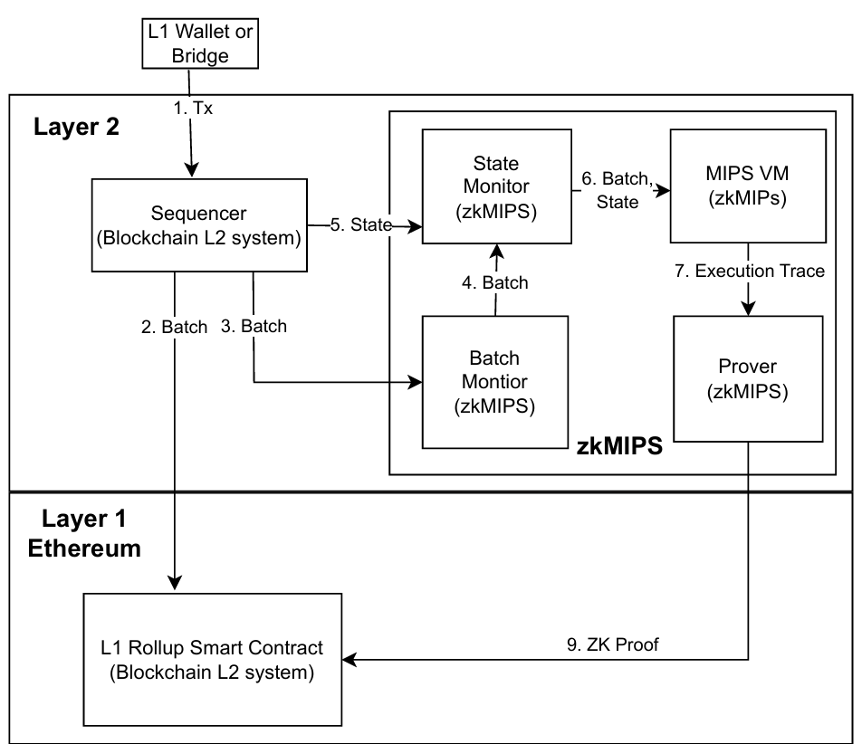
To connect zkMIPS with L2, users need to implement an L2-specific Communication Manager and a validation program for state transition. This program is then compiled to MIPS and executed by a MIPS VM. zkMIPS executes the program and generates ZK proof of execution. The proof can be sent to an on-chain proof verifier, which can trigger a state transition or allow withdrawals if the proof is valid. The main components of the integrated system are illustrated in Figure 3.
The main components of the system integration are explained as follow.
Fig. 3 illustrates zkMIPS workflow in the integration with L2 Rollup solutions. The parts which are coming from L2 technology stack are labeled with ‘(Blockchain L2 Sys tem)’. Also, the parts which are developed for zkMIPS are labeled with ‘(zkMIPS)’. The arrows show the general direction of the data flow.
Every ZK system comprises two main components: proof generation and proof verification. In this section, we explain the proof generation process. However, before delving into that, we provide an introduction to interactive and non-interactive ZKP approaches, followed by a review of our proof generation steps.
We first review some fundamentals before introducing the proof generation process.
Fiat and Shamir observed that the Prover can generate random bits by applying a hash function to the messages sent so far, simplifying the process [11]. For example, after sending the first messagem1, the Prover definesc1=h(public parameters, m1) as the Verifier’s first challenge. For the second message, the Prover computesm2, c2=h(c1, m2); for the third,m3, c3=h(c2, m3), etc. This creates a dependency on earlier messages due to the hash of a hash. In a non-interactive protocol, the Prover independently produces the protocol transcript public parameters, m1, c1, m2, c2, . . . , mn without requiring an actual Verifier. An external party can verify the correctness of the proof by replicating all of the Prover computations and confirming the accuracy of the final message mn.
Non-interactive methods offer several benefits over interactive methods. First, they eliminate the need for ongoing communication between the Verifier and Prover during the proof process. This simplifies the implementation and reduces communication overhead, making verification more efficient. Second, they enable the Prover to generate the entire proof transcript independently, without relying on the presence or availability of a Verifier. This self-contained nature allows for easier distribution and verification of proofs by third parties or independent verifiers [2, 24]. zkMIPS follows a non-interactive approach in its ZKP design.
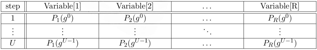
The overall state of an automaton is defined by the values of a finite list of variables. In this setup, a valid computation can be defined as a sequence of states from some well-defined initial state to a final state, in which each state transition represents a valid computation step. We can represent this valid sequence of states as a table whose columns represent the list of variables defining the automaton’s overall state and whose rows represent each step of the computation. This table is known as the execution trace.
We call the minimal set of automaton variables the CPU variables. Although it suffices to evaluate the execution of a program, we may choose to include in the trace an additional set of variables intermediary to the execution of each opcode from the program. We call this additional set the program variables and, in practice, it helps to evaluate the correct execution of programs by modeling some opcodes as sequences of more ZKP friendly operations.
Table 1 describes the list of columns/variables from each row/step of the execution trace. From this table, we can see that the execution trace contains the variables that are the CPU registers. Thus, it contains all the information necessary to independently verify each computation step.
The set of CPU registers from the execution trace is inspired by TinyRAM [6] as this architecture describes a minimal working CPU that is simple enough to be easily converted to STARK instances. The set of variables shown in Table 1 help to evaluate the correct execution of complex opcodes during ZKP steps.
We are now going to review our method. The first part applies the techniques described in [4, 5] by E. Ben-Sasson et al., [22] by StarkWare, and in [12, 23] by A. Gabizon et al. and Polygon. We then continue presenting our method in Section 4.3 to demonstrate our approach to generating a small-size proof. To start let’s review the basic terminologies.
Once the execution trace for an instance of the computation is defined, it can be converted to an input witness and follow the ZK steps to generate a proof.
The first phase of the protocol models the instructions of the input MIPS program as a set of polynomial constraints. These constraints serve as input for subsequent phases, ensuring the correctness of the protocol by accurately capturing the program logic. This phase algebraically compiles the program into a preliminary representation that needs to be proven. In summary, the Algebraic Intermediate Representation (AIR) [4, 5] is a polynomial representation specifically designed to facilitate efficient verification of large scale computations. We briefly summarize the applied steps as follows.
Note: This encoding proceeds using elements from \( G \), which means the \( j \)-th trace column \( \vec{x} = [x_1, \ldots, x_N] \) is encoded by \( P_j \) such that \( P_j (g^{i-1}) = x_i \). In addition, \( (P_1 (g^{i-1}), \ldots, P_R (g^{i-1})) \) and \( (P_1 (g^i), \ldots, P_R (g^i)) \) represent a valid state transition from state \( i \) to the next one if and only if Eq. Ⅱ holds.
\[ C_i (P_1 (g^{i-1}), \ldots, P_R (g^{i-1}), P_1 (g^i), \ldots, P_R (g^i)) = 0, \quad \forall i, \quad 0 < i < U \]
To summarize the described AIR steps as shown in Protocol Ⅱ
The explained steps allow the verification of subsequent computational states, we will follow an extended AIR approach that improves the described method by verifying dependency between non-subsequent states. Therefore, it reduces the number of necessary constraints.
Once AIR constraints have been generated, the protocol proceeds to a phase where a few additional constraints are considered, namely boundary, memory and general constraints that restrict the behavior of the polynomial at the edges of the computation domain, check the integrity of memory operations, and ensure generic constraints on all types of MIPS opcodes, respectively (see Appendix B for a formal definition).
In Algebraic Linking IOP (ALI), new constraints are defined algebraically and model the last properties that a correct execution of the target MIPS program must fulfill. Subsequently, all constraints are compiled into a polynomial comprising all of them by applying the random coefficients sent by the Verifier. Therefore, the Prover and the Verifier can finally engage in an Interactive Oracle Proof (IOP) to evaluate its validity.
We also apply the Domain Extending for Eliminating Pretenders (DEEP) method to prevent cheating in the opening phase of the ALI method \(\boxed{7}\). This method can be used to evaluate w.h.p. whether a committed polynomial function \(H \to \mathbb{F}\) indeed corresponds to a polynomial. It increases soundness of the system as it allows to verify in a single round that the rational function is not only close to a polynomial of degree at most \(d\), but is indeed a polynomial of degree at most \(d\). We can see this technique as an LDE being applied to the opening phase after the commitment phase. This domain extension only aims to catch cheating provers in the opening phase, since extending the commitment phase as well would require committing to the whole \(\mathbb{F}^* \setminus G\).
The idea behind this method is to sample points outside the box, where the box refers to \(G \cup H\) and the space we sample is \(\mathbb{F}^* \setminus (G \cup H)\) (remember that the polynomials input to ALI is LDEs from \(G\) to \(H\), so we consider a box containing both). More specifically, we let the Prover commit to some polynomial function \(f : H \to \mathbb{F}\) and check this commitment through a polynomial difference in \(f : \mathbb{F}^* \setminus G \to \mathbb{F}\), i.e. a difference between values from \(H\) and \(\mathbb{F}^* \setminus (G \cup H)\).
We apply DEEP-ALI method by Ben-Sasson et al. \(\boxed{4,5,7}\) which is summarized below.
An alternative way to constructfvalidity is by utilizing the Permutations over Lagrange bases for Oecumenical non-interactive arguments of Knowledge (Plonk) arithmetization [12]. Plonk arithmetization is gate-based, implying that the constraint polynomials aim to replicate circuit logic rather than CPU states as in AIR. In practice, the main distinction is that Plonk establishes constraints for each gate and employs selector polynomials to determine the gate logic/polynomial to be applied at each stage. On the other hand, AIR defines a distinct constraint polynomial for each computation step, modeling the permissible state transition.
Plonk is a SNARK (Succinct Non-Interactive Argument of Knowledge) proof system that incorporates a universal and updatable trusted setup. This means that the trusted setup process can be performed once and then reused for all subsequent computations involving circuits of smaller sizes compared to the original computation [12].
In the initial phase of the system, the instructions of the input program are modeled as an "arithmetic circuit" format. After generating these gates for the circuit, assuming left and right inputs and an output for each gate, an execution trace table, denoted as \( A = [A_{ij}] \), \( i = 1, \ldots, V \), \( j = 1, 2, 3 \), is created. In this table, the values of \( A_{i1}, A_{i2}, \) and \( A_{i3} \) correspond to the input and output wires of the \( i \)-th gate, respectively.
The subsequent phase involves transforming the arithmetic circuits into a constraint system. This system comprises two types of constraints: gate constraints and copy constraints. Each gate constraint corresponds to a specific gate in the arithmetic circuit. On the other hand, copy constraints relate to different gates, for example the output of gate \( i \) which should be the same as the left input of gate \( i + 1 \). The copy constraints guarantee that the values in the wires remain consistent throughout the computation. An example of a system with addition and multiplication gates are as described in Protocol 3.
The copy constraints are implemented using polynomials that encode a deterministic ordering of gate inputs and the same ordering permuted by their respective wires. Then, it must be checked whether such a permutation holds, which can be done with an auxiliary accumulation polynomial and a specific protocol to evaluate the final accumulated value. An example of a system with two-input and one-output gates are as described in Protocol 4.
Note that Protocol 4 is executed at most six times to handle different copy constraints, which are defined as follows: 1) left inputs \( Q_L(g^{i-1}) = Q_L(g^{\sigma_{Q_L, Q_L}(i-1)}) \), 2)
right inputs \( Q_R(g^{i-1}) = Q_R(g^{\sigma_{Q_R, Q_R}(i-1)}), \) 3) outputs \( Q_O(g^{i-1}) = Q_O(g^{\sigma_{Q_O, Q_O}(i-1)}), \) 4) left and right inputs \( Q_L(g^{i-1}) = Q_R(g^{\sigma_{Q_L, Q_R}(i-1)}), \) 5) left input and output \( Q_L(g^{i-1}) = Q_O(g^{\sigma_{Q_L, Q_O}(i-1)}), \) 6) right input and output \( Q_R(g^{i-1}) = Q_O(g^{\sigma_{Q_R, Q_O}(i-1)}). \) After executing Protocol 4 for the various copy constraints, the system continues by running Protocol 5 to combine the copy constraints.
The gate-based arithmetization employed in Plonk makes it well-suited for algorithmic descriptions that resemble circuits. However, when it comes to algorithmic descriptions resembling CPU operations, the utilization of Plonk arithmetization requires the inclusion of additional copy constraints. These constraints are necessary to ensure that register values remain unchanged when they are not intended to be modified.
We continue the system by applying the Fast Reed-Solomon IOP of Proximity (FRI) technique. In FRI, the Prover aims to prove the closeness of \( f_{\text{validity}} \) to low-degree polynomials. In fact, it aims to prove that it is close to a polynomial of low degree instead of verifying that \( f_{\text{validity}} \) is of low degree \(\boxed{3}\). For this section, we follow the method described in [20] by Masip-Ardevol et al. and [16] by Haböck. We first review the general approach and then explain it in Protocol \(\boxed{6}\).
The idea is that the Prover splits a polynomial \( g_i \) into even and odd polynomials, according to the degree of each of its factors. Namely, \( g_i \) is split into \( g_{i,1}, g_{i,2}: H_{i+1} \to \mathbb{K} \) where \( H_{i+1} = \{ x^2 \mid x \in H_i \} \) and \( \deg(g_{i,1}), \deg(g_{i,2}) \leq \frac{1}{2} \cdot \deg(g_i) \). Algebraically, \( g_i \) can be represented as a combination of \( g_{i,1} \) and \( g_{i,2} \) as in Eq. [10]. Then, the Prover substitutes this factor \( x \) by some value \( v_i \in \mathbb{K}^* \) randomly chosen by the Verifier, denotes the resulting polynomial by \( g_{i+1} \), as in Eq. [11] and commits to it
\[ g_i(x) = g_{i,1}(x^2) + xg_{i,2}(x^2) \]\[ g_{i+1}(x) = g_{i,1}(x) + v_i g_{i,2}(x) \]
Note that the procedure above will be performed repeatedly for a number of \( l = \log(d) \) times where \( d = \deg(f_{\text{validity}}(x)) \). Furthermore, the PCS we use to commit to each \( g_i \) is a Merkle tree with \( M \) leaves. When the Verifier queries \( g_i(s), s \in H_i \), the Prover can simply respond with the Merkle path corresponding to the leaf of \( g_i(s) \). In summary, FRI is shown in Protocol \(\boxed{6}\).
Finally, to prove and verify the validity of the whole MIPS program execution with soundnessϵ, the Prover and the Verifier engage in Protocol 8.
zkMIPS utilizes two main proof generation methods: Starky and Plonky2. Starky consists of the AIR, ALI, and FRI parts, as explained in the previous sections. On the other hand, Plonky2 is a SNARK proof system that combines the Plonk and FRI parts. It is worth noting that FRI does not require a trusted setup. With this introduction, we will explain the zkMIPS proof generation architecture in the next section that applies Starky and Plonky2 methods.
We first focus on the composition step. Different types of ZK proof require different amounts of resources, such as memory, prover time, verifier time, proof size, and gas cost (for L1), among others. Proof composition allows us to combine two different types of proof, creating the best of both worlds.
As an example, consider a proof \( \pi_b \) of the correctness of the execution of a batch of transactions. When STARK is applied, a large proof is generated (considering the required blow-up factor), resulting in longer verification times. The Prover can execute the verification process using its own generated proof, \( \pi_b \), and provides a new proof \( \pi_v \) demonstrating the correctness of running the verification process. Since the second proof is meant to show the correctness of a fixed verification program, it can be optimized to provide a shorter proof size when combined with \( \pi_b \). Finally, \( \pi_v \) can be verified by an actual verifier, as shown in Figure 4.

In the recursion stage, the first proof is generated by the first Prover using program execution. Then, the output proof is passed as input to the proof generation process, and the process is recursively repeated. Figure 5 shows the process of recursive provers.

By employing an aggregation technique, multiple proofs can be combined and aggregated into a single proof. This consolidated proof can be verified in a single step, thereby reducing the overall cost of verification. The aggregation technique also offers the advantage of generating proofs for smaller batches of transactions. As a result, the proving time is significantly decreased compared to generating a proof for a large batch of trans actions [8, 15, 18].
We want to use composition, recursion, and aggregation to prove the correct execution of several batches of transactions. Figure 6 shows the overall process.
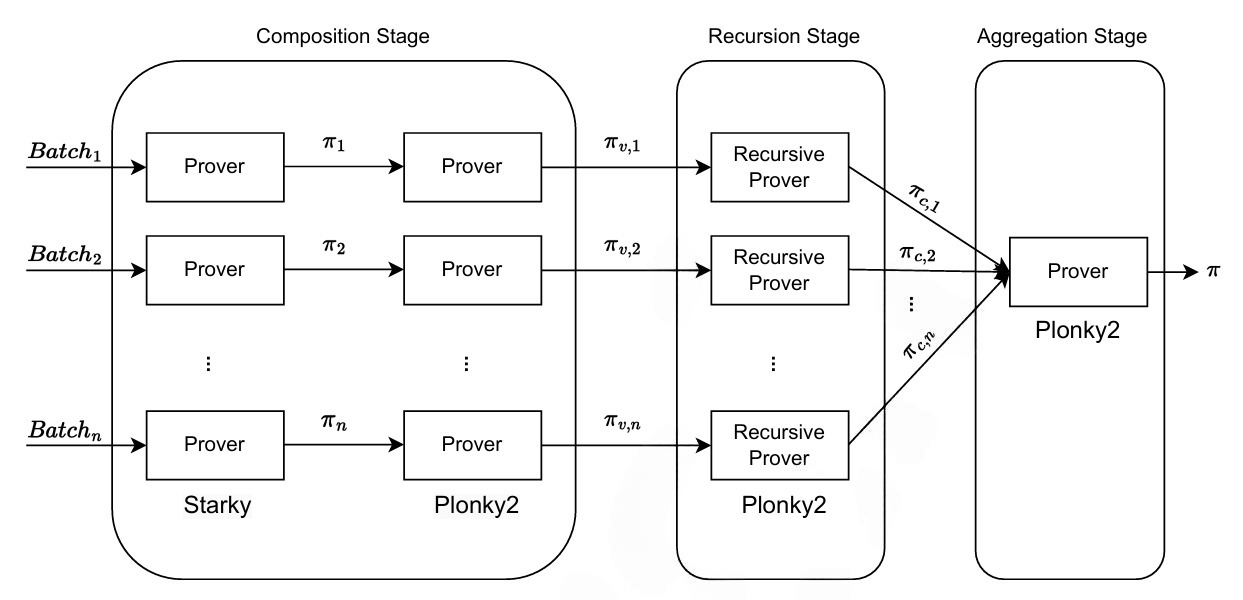
Confirmed transactions are batched to \( n \) batches; consequently, we can compute STARK proofs \( \pi_1, \pi_2, \ldots, \pi_n \) for each of these batches in parallel. In the composition stage, the system generates \( \pi_{v,1}, \pi_{v,2}, \ldots, \pi_{v,n} \) with a compressed and normalized size.
The resulting normalized and compressed proofs \( \pi_{v,1}, \pi_{v,2}, \ldots, \pi_{v,n} \) can be further optimized by applying \( k \) steps of recursion. Now, the resulted proofs \( \pi_{c,1}, \pi_{c,2}, \ldots, \pi_{c,n} \) can be used in batching step to make them into one proof and then, validate only the final proof \( \pi \). Finally, the outputs of the recursion stage \( \pi_{c,1}, \pi_{c,2}, \ldots, \pi_{c,n} \), can be aggregated into a single efficient proof \( \pi \) in the aggregation stage.
zkMIPS has valuable applications in Layer 2 (L2) blockchain solutions. L2 solutions aim to alleviate the scalability limitations of the underlying Layer 1 blockchain by processing transactions off-chain. Using zkMIPS, participants can cryptographically prove the validity of off-chain transactions in the Ethereum blockchain without revealing the specific details of each transaction on the public blockchain. This ensures the integrity of transactions. In addition, multiple transactions can be aggregated into a single proof, reducing the computational overhead required for verification and enhancing scalability. The provided proof guarantees the correctness of the transaction execution and hence reduces the withdrawal time of the processed fund. Fig. 7 provides an overview.
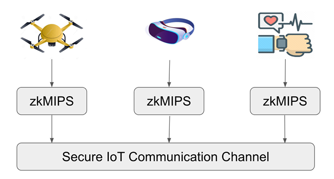
zkMIPS, utilizing the MIPS instruction set, holds promises to add verifiable computing functionalities to IoT, VR, and wearable devices that incorporate MIPS processors. In the realm of IoT, zkMIPS can offer secure and privacy-preserving communication protocols for connected devices. By leveraging ZKP, zkMIPS can enable secure data exchange, authentication, and integrity verification within IoT networks. This ensures that sensitive information remains confidential and protected against unauthorized access.
In the context of Virtual Reality (VR), zkMIPS can contribute to improved privacy and security in VR environments. zkMIPS can enable users to interact and engage in virtual experiences while maintaining the confidentiality of their personal data and activities. This includes safeguarding sensitive user information, such as biometric data or behavioral patterns, from potential threats. One such application can be explained through VR concerts that are rising in popularity. In one such example, a concert organizer may want to issue tickets in the form of non-fungible tokens (NFTs) to concert givers, but to avoid keeping data due to General Data Protection Regulation (GDPR) and other information laws, they can utilize this feature in order to register concert attendees through the public addresses of these NFTs - due to power of zero-knowledge, the organizer only needs the proof that a ticket has been paid for by a certain address, while the attendee can enjoy the concert live, without worrying about whether their data are being tracked.
Furthermore, in wearable devices that utilize MIPS architecture, zkMIPS can offer privacy-enhancing features and provide secure and private interactions with connected devices and networks. This can be particularly crucial for wearables that handle sensitive user data, such as health-related information or personal fitness metrics. Fig. 8 provides an overview.
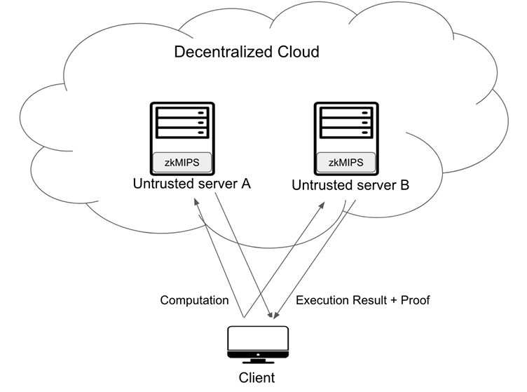
zkMIPS introduces an exciting opportunity for decentralized cloud computing systems. With zkMIPS, the computations can be offload to the cloud, leveraging the power of thousands of untrusted processors to execute them swiftly. Despite the untrusted nature of these processors, the computation result can still be trusted when using zkMIPS. This breakthrough paves the way for innovative applications in secure and scalable cloud computing.
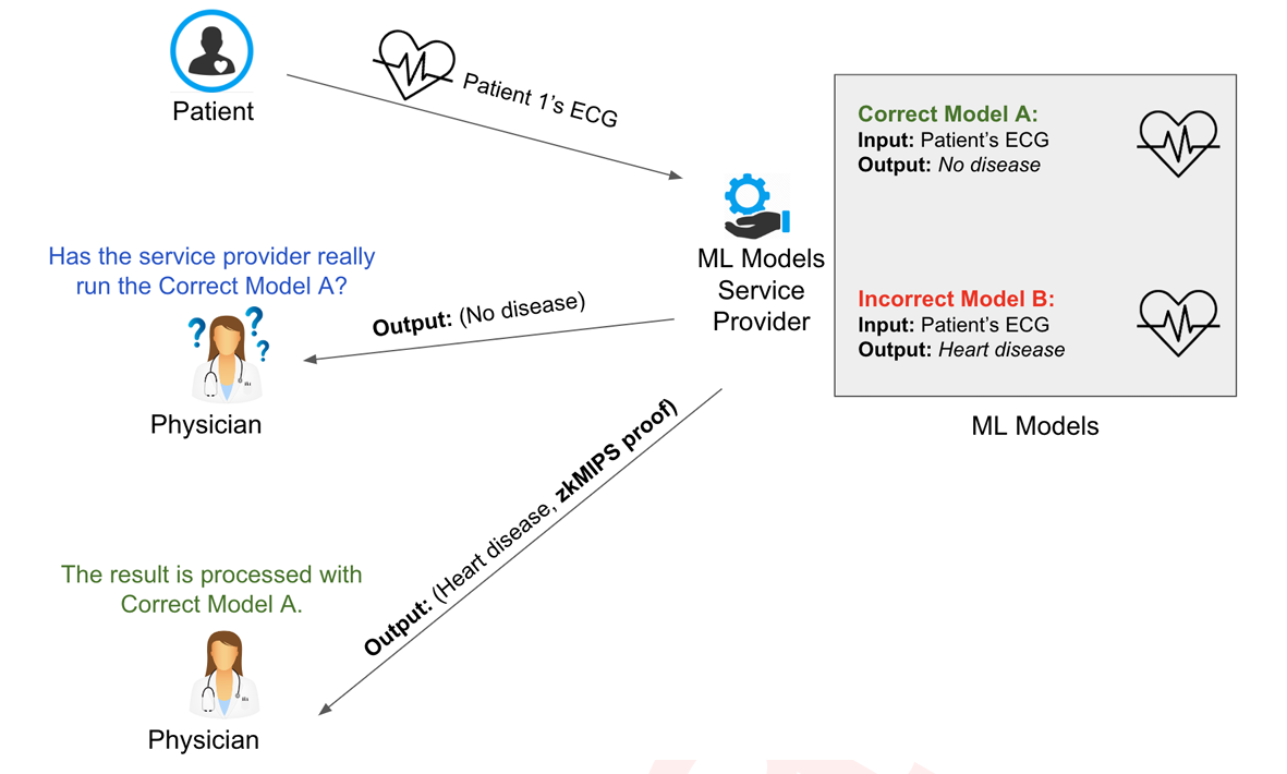
In the machine learning (ML) world, the use of ZKP has the potential to verify the application of a given ML model or hide the user’s valuable data. This is referred to as zero-knowledge machine learning (zkML). Since the weight values within an ML model are considered proprietary information held by service providers, clients should have the means to verify the correctness of the results without accessing the trained model. Moreover, when a third party examines the results, it should be possible to confirm their accuracy even without the user’s input data [19]. Figure 10 shows a scenario in medical systems where a patient sends their ECG to an ML Service Provider, and the processed result is sent back to their physician. As depicted, the physician requires a means to verify the correctness of the process.
The utilization of zkMIPS can be expanded across various applications and scenarios. Consequently, it has become crucial for users to take advantage of ML computations without revealing the input values in order to preserve users’ privacy.
This document provides an overview of the steps involved in the zkMIPS zero-knowledge architecture. As the project continues to evolve, we anticipate updating this document on a monthly basis or more frequently, if necessary.
We are also aware that other teams are simultaneously working on implementing new techniques and solutions that could significantly improve the performance of zkMIPS. We closely monitor the progress of these projects to evaluate their potential integration into zkMIPS as soon as the corresponding software libraries or final techniques become accessible. If such an integration occurs, we will report on it in this document.
We would like to acknowledge the MetisDAO Foundation for its support in the zkMIP project. Their participation has been instrumental in advancing the project’s goals. We appreciate the guidance and assistance provided by them throughout this journey.
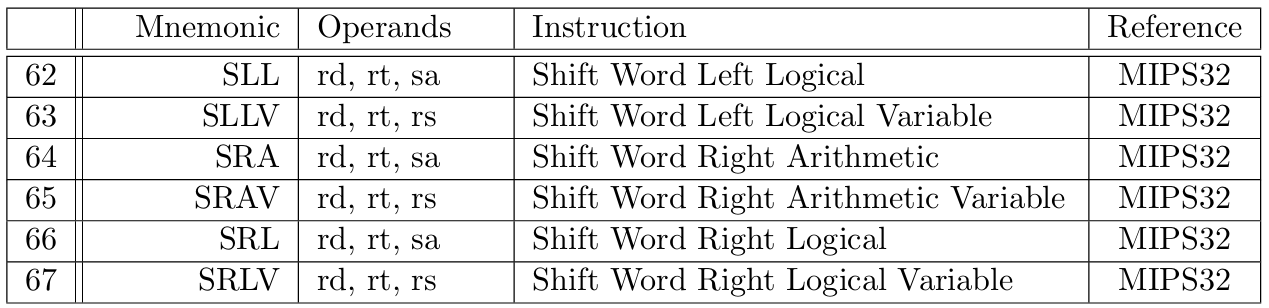
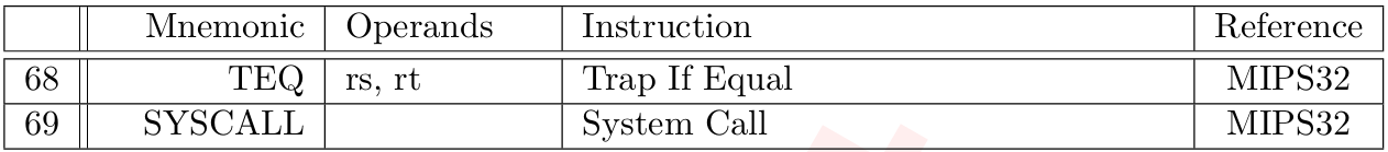
Tables 3 to 10 describe instructions from our MIPS Instruction Set, classified according to [17]. A detailed description for each instruction can be found in the MIPS32 [21] or MIPS R3000 [17] documentation, as specified in the last column of each instruction row.

To ensure the correct execution of MIPS program and make the execution trace to ALI constraints transition smoother, zkMIPS supports the following additional types of constraints:
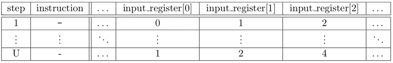
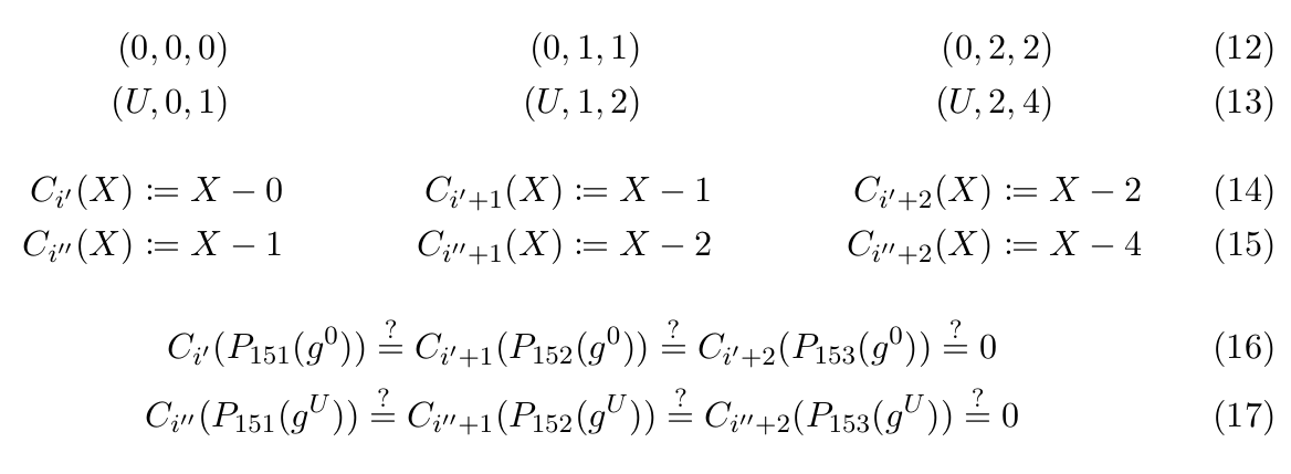
Boundary constraints ensure registers take certain values at certain steps. Typically, these constraints verify that the correct values were input and output to the first and last steps of the execution trace, respectively, as in Table 11. The Boundary constraints can be annotated as tuples (i, j, α), meaning that at thei-th step thej-th register should take the valueα (Equations 12 and 13). Then, following the indexing from Table 1, they can be expressed as constraint polynomials (Equations 14 and 15) and verified as polynomial evaluations (Equations 16 and 17).
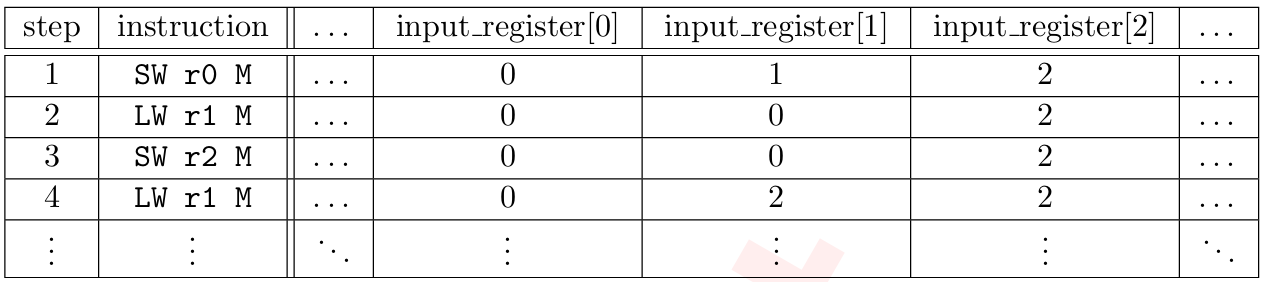
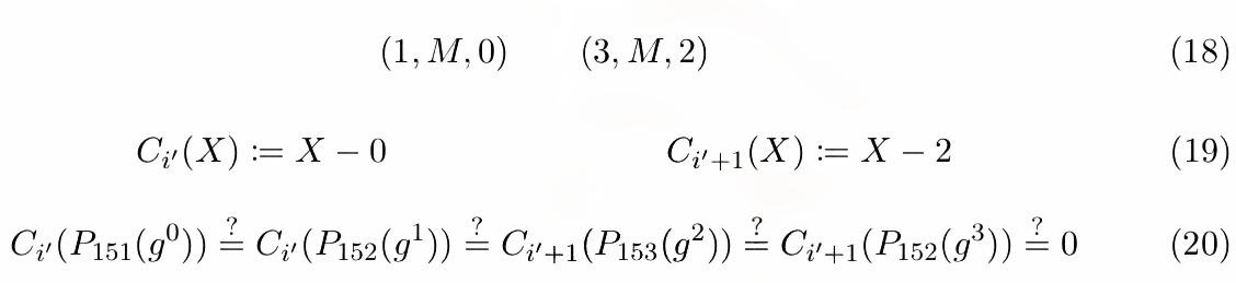
Memory constraints ensure values loaded from memory positions match the latest values stored there. Just like boundary constraints, memory constraints can be annotated as tuples (Table 12 and Equation 18) and implemented as polynomial constraints (Equations 19 and 20) additionally sorted by ascending memory locations and time. By analyzing memory transcripts, it is possible to verify the consistency of memory locations during execution.
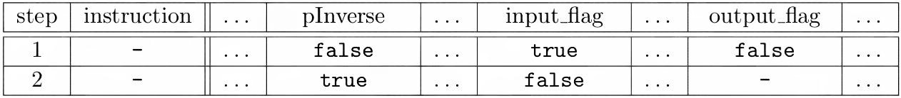
General constraints ensure generic constraints on all type of MIPS opcodes such as flag constraint, if-else conditions with respect to range of values that opcode accept, etc. Just like boundary and memory constraints, general constraints can be annotated as tuples (Table 13 and Equation 21) and implemented as polynomial constraints (Equations 22 and 23).